mr
.
steam
®
C U S E R I E S Installation, Operating & Maintenance Manual
13
American College of Sports Medicine Health/Fitness
Faculty Standards and Guidelines, or a similar resource
and reference publication, and refer to those guide lines
for the proper and safe operation of a spa facility includ-
ing steam rooms. Steam room construction information is
avail-able from the Tile Council of America, Inc. at (864)
646-8453 or www.tileusa.com.
The Digital 1
®
Temperature Control System
is required operating equipment for each steam room.
The operating temperature control is to be set by the
owner/operator to sense desired room temperature at
the sensor location within the steam room. Connection of
the Over Temperature portion of the Digital 1 control is
mandatory to provide additional protection to the
bathers. The steam room is to be operated in accor-
dance with “Important” information as noted above.
IMPORTANT:
Final selection of the steam room temperature setting is
at the discretion of the owner/operator.
Ensure all splices in the sensor cable are
securely crimped soldered and sealed with heat
shrink tubing.
CONTROL CIRCUIT WIRING DIAGRAM
SEE PAGES 11, 12 & 13 FOR DIAGRAMS
Installer shall use a safety switch of ade-
quate capacity employing suitably rated circuit breakers
or fuses between main electrical power source(s) and the
generator. Location of safety switch to be in accordance
with National and local electrical codes.
NOTES:
1. Larger rooms may require two or more steam solenoid
valves in parallel.
2. When generator services two rooms, second room
requires a set of Digital 1
®
and solenoid valves.
IMPORTANT:
3. Digital 1
®
sensors are intended to be field installed
within the steam room at the location selected by the
designer/architect. DO NOT LOCATE THE Digital 1
SENSOR NEAR OR ABOVE THE STEAMHEAD(S) AS
THIS MAY CAUSE DIRECT STEAM EMISSION TO
INTERFERE WITH STEAMROOM TEMPERATURE REG-
ULATION.
4. Autoflush System 24 hr. timer and Digital 1
®
operating
settings are at the discretion of the owner/operator.
IMPORTANT: Owners/operators should obtain a copy
and familiarize themselves with the latest edition of the
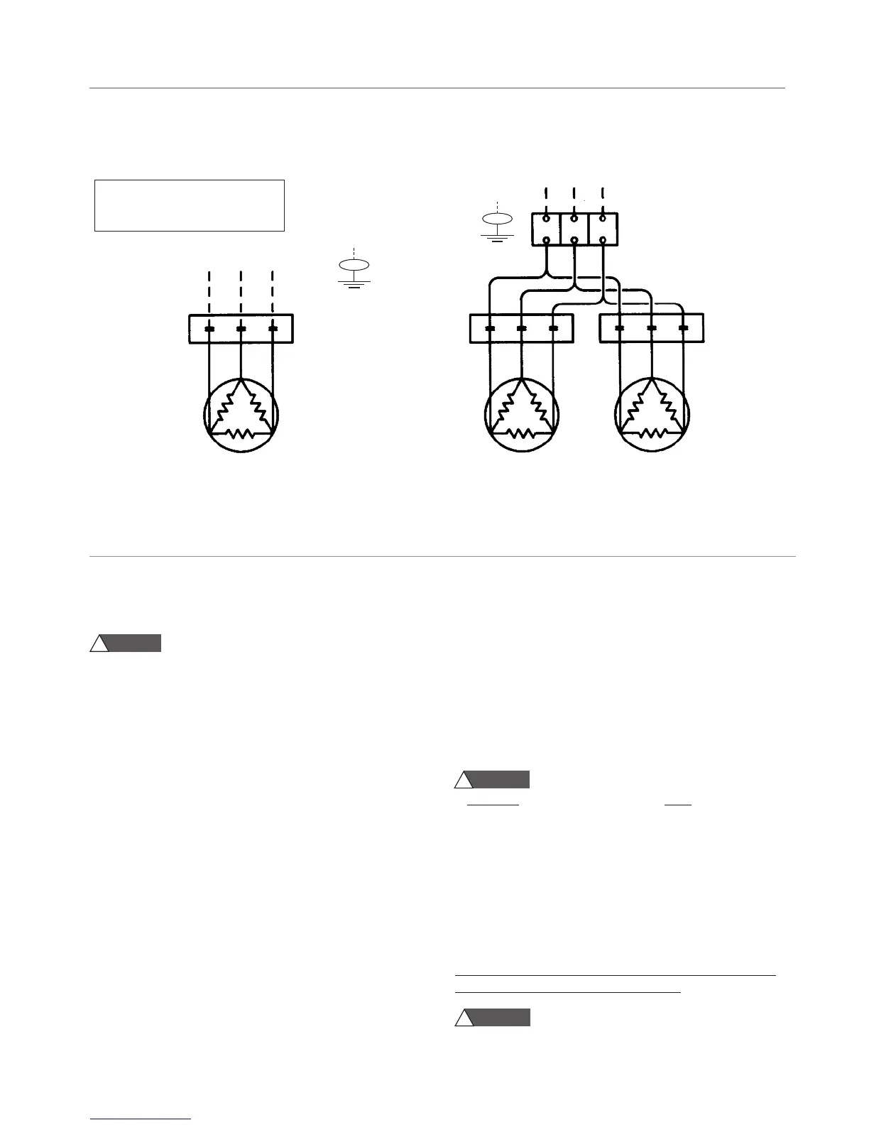
3PH Power Supply
Power Contactor
Heating Element
Diagram #1
Units with 1 Contactor (see note 1)
3PH Power Supply
Power Terminal Block
Power Contactors
Heating Elements
Diagram #2
Units with 2 or more Contactors (see note 1)
GRD
GRD
__ __ __ __
Field Wiring
__________
Factory Wiring
IMPORTANT:
Also refer to Control Circuit diagrams in this manual.
TYPICAL POWER WIRING DIAGRAM
WARNING
!
WARNING
!
CAUTION
!