mr
.
steam
®
C U S E R I E S Installation, Operating & Maintenance Manual
16
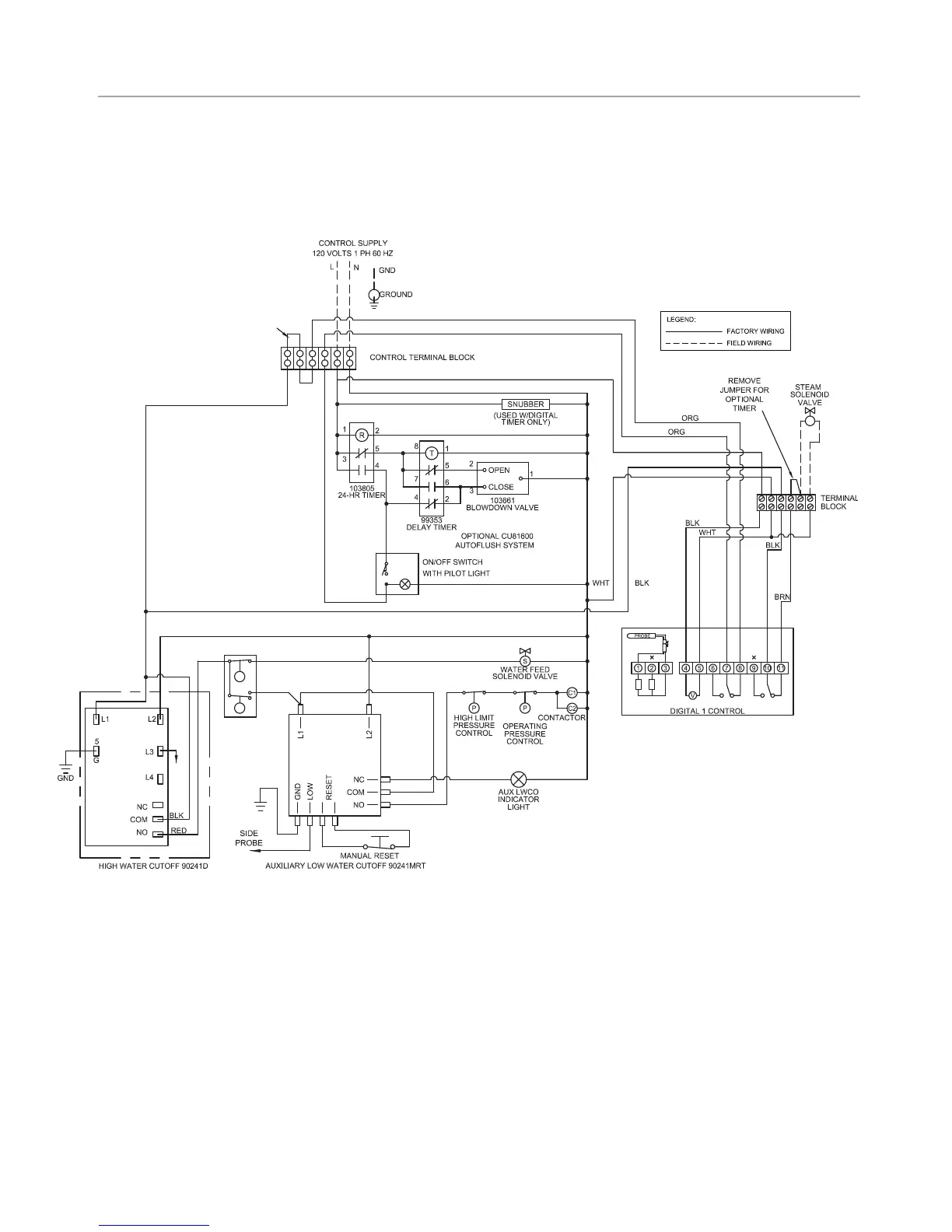
CONTROL CIRCUIT WIRING DIAGRAM
Models CU-2000 and higher with Digital 1
®
Temperature Control System
and Optional Automatic Blowdown Assembly
IMPORTANT:
1. Digital 1
®
sensors are intended to be field installed within the
steam room at the location selected by the designer/architect.
DO NOT LOCATE THE Digital 1 SENSORS NEAR OR ABOVE THE STEAMHEAD(S) AS THIS MAY CAUSE
DIRECT STEAM EMISSION TO INTERFERE WITH STEAMROOM TEMPERATURE REGULATION.
2. Autoflush System 24 hr. timer and Digital 1 operating settings are
at the discretion of the owner/operator.
IMPORTANT: Owners/operators should obtain a copy and familiarize |
themselves with the latest edition of the instruction manual.
REMOVE JUMPER
FOR 2nd OVER TEMP.
SHUT OFF
HIGH
PROBE
(PNK)