mr
.
steam
®
C U S E R I E S Installation, Operating & Maintenance Manual
17
D
igital 1 Sensor
Digital 1 Control and 30 ft. Cable Acrylic Shield
3
⁄4"
Steam Solenoid Valve Digital1 Sensor Cover
3
⁄4"
Steam Head
Digital 1 Sensor
Digital 1 Control and 30 ft. Cable Acrylic Shield
3
⁄4"
Steam Solenoid Valve Digital1 Sensor Cover
3
⁄4"
Steam Head
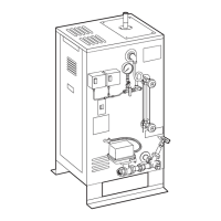
NOTE:
FOR ILLUSTRATIVE PURPOSES ONLY.
Optional equipment shown. Consult with qualified designer,
architect or contractor for steam room construction details,
including location of steam head(s) and sensors.
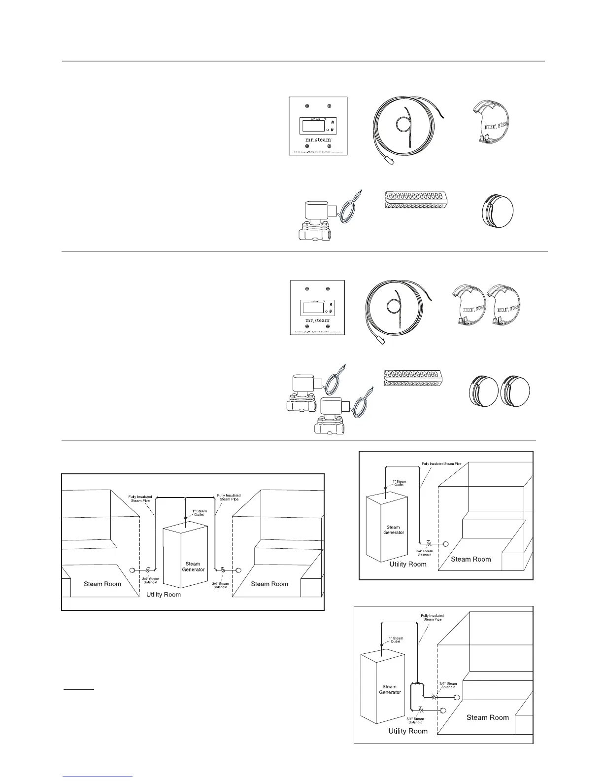
DIGITAL 1
®
KIT
Mr. Steam CU Steambath Generator can be used
for one or two steam rooms in accordance with
guidelines for generator selection on page 6. Each
room requires one Digital 1 Kit sized for the room.
S
ee page 4 (figure 1) for typical installation.
DIGITAL 1 KIT CONTENTS:
• Digital 1 Control (factory installed on generator)
• Digital 1 Sensor
• One 3/4" Steam Solenoid Valve and 3/4" Steamhead
• Acrylic Shield
• Sensor Cover
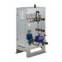
CU2 - DIGITAL 1
®
KIT CONTENTS
CU 2000–4500 serving one room using two steam
solenoid valves and two steamheads.
CU2-D1 KIT CONSISTS OF:
• Digital 1 Control (factory installed on generator)
• Digital 1 Sensor
• Two 3/4" Steam Solenoid Valves and 3/4" Steamhead
• Two Acrylic Shields, one for each steamhead
• Sensor Cover
TYPICAL INSTALLATIONS
Double steam rooms, single steam head (2x CU1-D1)
Single steam room, single steam head (CU1-D1)
Single steam room, double steam head (CU2-D1)