mr
.
steam
®
C U S E R I E S Installation, Operating & Maintenance Manual
22
OPERATION INDICATORS
O
UT 1: The LED under OUT 1 is on during normal operating
c
onditions. If the light under OUT 1 is off the Digital 1 is in
b
ackup temperature mode, an alarm will sound, the display will
f
lash and the steam bath generator will be off.
OUT 2: The LED under OUT 2 goes on and off during normal
operating conditions. If the light under. OUT 1 is off the room
temperature is satisfied and the steam solenoid valve will be
closed. When the light under OUT 2 is on the room tempera-
ture has not been satisfied and the steam solenoid should be
open (if a 30 minute timer is used, that must be on to open the
steam solenoid).
BACKUP TEMPERATURE SHUT-OFF
• Digital1
®
Control will shut off power to the steam bath generator.
• The display will change to a flashing AH1, and an alarm will
sound (if equipped the CU ALARM will also sound.
• To silence the Digital 1 Control Alarm press SET and DOWN
simultaneously. The alarm will be silenced but the display will
still flash AH1 and the steam bath generator will remain off.
*Note if equipped with a CU ALARM turn the steam bath genera-
tor switch off to silence it.
• The Digital 1 control will reset when the temperature in the room
reaches normal operating range.
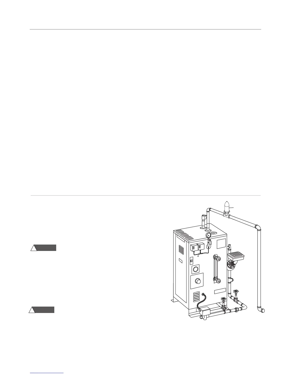
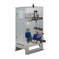
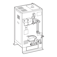
Steam Generator
Steam Vent
30 MINUTE ROOM TIMER
The 30 minute timer provides guests in the steam room an accurate and
easy way to safely time their steam sessions. It is available as a Digital
(CU-99216DIG) or Mechanical (CU-99216B) timer.
1. This timer may only be fitted by a qualified electrician.
Shock hazard! This timer uses the specific supply volt-
age. Fit the timer appropriately before connecting it to the main sup-
ply. Never touch the live contacts or components at the open back of
the timer.
2. Protection against touch contact must be ensured by a proper mount-
ing. When fitting the timer, make sure that during normal operation it is
impossible for the end user of the steam generator it was fitted in to
remove the timer by pulling it to the front and exposing the live parts.
3. Avoid any contact of the timer with water.
The 30 Minute Timers shall not be installed inside the steamroom.
4.
IMPORTANT:
A steam vent (PN 104072) must be installed in the steam line
between the steam generator and the steam solenoid valve when using a 30
minute timer as shown.
NOTE:
See the Operating Manual for the Digital Timer (PUR 100383) for com-
plete installation instructions.
NOTE: All drawings are for illustrative purposes only.
WARNING
!
WARNING
!
M
ESSAGE DISPLAY
Under normal operation, the actual room temperature will be
displayed, the following messages may also appear (the Digital1
Control alarm will also sound, press SET and DOWN simultane-
ously to silence alarm, if equipped with a CU ALARM turn the
s
team bath generator switch OFF to silence it, the steam bath
generator will shut off until the error is cleared):
_
_______________________________________________________________________________
• Err Memory reading error, cut power to control to clear
_
_______________________________________________________________________________
• AH1 Backup temperature alarm
_
_______________________________________________________________________________
• AL1 (AL2) Low temperature alarm, this may be an indication
of a probe problem, check the actual room temperature
_
_______________________________________________________________________________
• ooo Open Probe, check probe connection, check probe
with multimeter
_
_______________________________________________________________________________
• ––– Shorted probe, check any splices used, check probe
with multimeter (NOTE: if equipped with CU STEAMSTOP, the
Digital 1 Control will display --- when the CU STEAMSTOP is
pressed, reset the CU STEAMSTOP to clear)
________________________________________________________________________________
NOTE: The operating room temperature setting is deter-
mined by the owner/operator of the facility. For guidance,
refer to ASCM guidelines or equal reference.