mr
.
steam
®
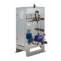
C U S E R I E S Installation, Operating & Maintenance Manual
23
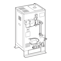
PRESSURE CONTROLS OPERATION
AND TESTING
Steambath generators are provided with one hi-limit pressure control
and at least one operating pressure control.
1. All pressure controls are equipped with a screw allowing for setting
of the desired operational and hi-limit pressures.
2. It is recommended that the hi-limit control be set at 8–10 psig maxi-
mum and the operating pressure control(s) shall not be set above 5
psig.
NOTE: Models CU360 - CU3000 are provided with one (1) automatic
reset operating pressure control and one (1) manual reset high limit
pressure control. Models CU 4500 is provided with two (2) automatic
reset operating pressure controls and one (1) manual reset high limit
pressure control.
3. Pressure control operation check: Manually close the steam
outlet valve. Switch the generator on to allow for steam pressure
build-up. Pressure gauge reading will build and the operating pres-
sure control will shut off the generator at the pressure setting. Re-
setting the operating pressure control is accomplished by manually
bleeding off pressure through the steam outlet valve and allowing
the pressure to drop below the desired set point.
TORQUE VALVES
Check to insure all element flange bolts, element terminals, and con-
tactor terminals are tightened to the following specifications.
IMPORTANT:
See page 29 for
additional information
and illustrations.
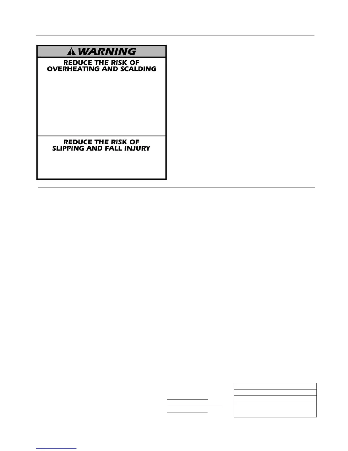
WARNING SIGNAGE
T
he CU Steambath generator is provided with a
WARNING sign. This WARNING is to be secured
to the outside of the steam room, on the steam-
room door or adjacent to that door. It's location
must be such that all steam bathers are readily
made aware of the important information con-
tained in the sign.
TORQUE VALUES
Element Flange Bolts 22 lb-ft
Element Terminals 20 lb-in
Contactor Terminals : Tighten to
torque specified on contactor.
1
. Exit immediately if uncomfortable, dizzy or sleepy. Staying too long in a heated
a
rea is capable of causing overheating. Limit yourself to a maximum of ten
(
10) minutes. High temperature and humidity can be dangerous to your health.
2. Children under the age of 16 should not use this facility.
3
. Check with a doctor before use if pregnant, diabetic, in poor health or under
m
edical care.
4. Breathing heated air in conjunction with consumption of alcohol, drugs
or medication is capable of causing unconsciousness. Therefore, do not use
this facility if you have recently consumed alcohol, drugs or medications.
5
. Do not contact steam head or steam at the steam head.
6. Allow yourself at least five (5) minutes after exercising to cool down before
entering this facility.
U
se care when entering or exiting the steam room. Floors may be slippery and
dangerous due to moisture. Use of proper footwear is recommended at all times.
Note: For additional safety considerations see Owners manual.
mr
.
steam
®
4
3-20 34th Street, Long Island City, NY 11101 1-800-76-STEAM www.
m
rsteam.com
PRE-OPERATION CHECK
Low water Cutoff (LWCO) and
Feed Control Operation and Testing
1. All valves for incoming water supply are to be fully
opened. Main disconnect switch to be in "ON" posi-
tion. Generator switch to be in “ON" position. Since
generator will be empty, water solenoid will be ener-
gized allowing the generator to fill with water until
proper level is reached. Then the contactors will ener-
gize and supply voltage to heating elements.
2. Water level control operation: At this point the water
should be visible approximately half way up the sight
glass. Slowly open the drain valve located at bottom
of the generator. The water level will fall allowing the
low water cutoff/water level control to energize the
feed water system. Close the drain valve for proper
operation.
3. Low water cut-out switch performance. Close water
feed valve. Open the drain valve completely. Maintain
this condition until the water level falls within the
gauge glass enough to cause the low water cutout
switch to de-energize the heating elements. All con-
tactors will be in the de-energized state at this time.
Close the drain valve. For automatic re-setting type
low water cutoff switches, feed system will return the
water level to normal. For manual re-set the reset but-
ton must be depressed to complete circuit. The gen-
erator is now qualified for proper low water cutout
and normal liquid-level operating conditions.
NOTE: For automatic blowdown, turn timer off and on
until water level is low enough to de-energize heaters.