33
mr
.
steam
®
C U S E R I E S Installation, Operating & Maintenance Manual
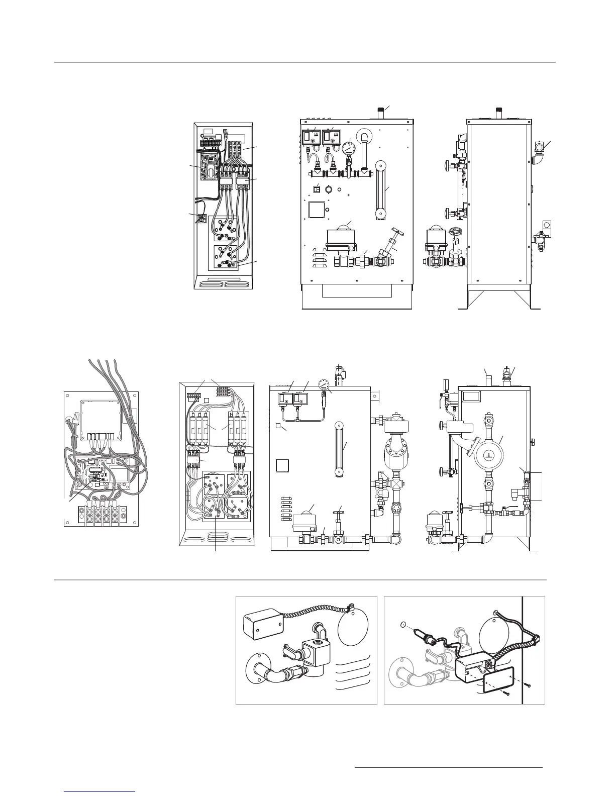
CU 360-1400 Typical
Component
Arrangement
CU 2000-4500 with
Digital 1, Clock and
Blowdown
All drawings for illustrative purposes only.
Contactor
Terminal
Block
Fuses
Heating
Elements
Front Right Side
G
A J
H
B
L
K
D I
C
F E
A
F
E
G
Front Right Side
J
H
K
C
I
D
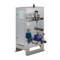
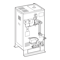
Install probe, junction box and cableCompleted Assembly
Auxiliary Manual Reset
Low Water Cutoff
• Available on CU 2000-4500
• For CU 2000-3000 a block off
plate is used where the junction
box is shown
• For CU 4500 there is a junction
box as shown.
Blowdown
Control Panel
Time Delay
Relay Board
Terminal
Blocks
Contactors
Heating
Elements
Liquid
Level
Control
Board
AUX
LWCO
LABEL FUNCTION
A Steam Outlet
B Water Inlet
C
Drain Outlet
D
Optional Automatic
Blowdown Valve
E High Limit Pressure
Control
F Operating Pressure
Control
G Pressure Gauge
H Gauge Glass Assembly
I Drain Valve
J Safety Valve
K On/Off Switch
L Mechanical low water
cutoff and feeder
(MM150)