CU AUTOFLUSH
GRNWHTBLKBRN
Blowdown
Control Panel
Terminal Block
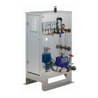
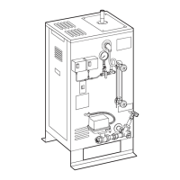
in Steam Generator
Panel Interior
Remove Jumper
Snubber
(see note 4)
mr
.
steam
®
C U S E R I E S Installation, Operating & Maintenance Manual
20
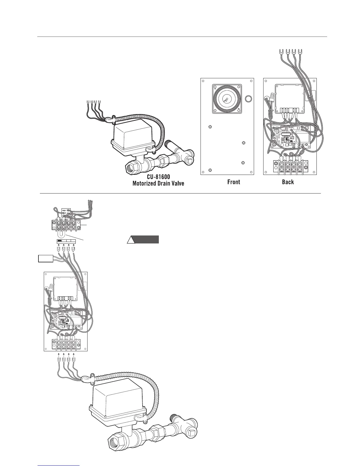
AUTOMATIC BLOWDOWN SYSTEM
CU 81600
T
he Automatic Blowdown System consists of the following factory installed items:
•
Blowdown Control Panel
•
Motorized Drain Valve Assembly #CU-81600
NOTE: If the steam generator came with a factory installed Automatic
Blowdown System see page 24 on how to program the timer.
Hazard of Electric Shock. Disconnect all power supplies before
making wiring connections. NOTE: Reference applicable wiring diagram.
1. Remove blank cover and mount the Automatic Blowdown Control Panel on the front
of the generator cabinet with screws and nuts provided.
2.
Remove the jumper between Brown & Black from the terminal block above the panel.
3. Connect the wires to the terminal block. The terminals are coded with the wire
insulation color: Brown-Black-White-Green.
4. When using the Digital Blowdown timer (PN 103662) install the Snubber (PN 104251)
between the black and white terminals.
5. Plumb the motorized valve assembly to the generator drain valve.
6. Install the valve cable in the knockout below the Automatic Blowdown Control Panel.
7. Connect the wires to the terminal block at the bottom of the panel. The terminals are
coded with the wire insulation color. CU81600: White-Blue-Red-Green
8. Program the timer and set the clock (See page 24)
AUTOMATIC BLOWDOWN SYSTEM KIT INSTALLATION
CU-81600 Motorized
Drain Valve Assem
bly
WARNING
!