MSA DESCRIPTION
ALTAIR 4 - Operating Manual 11
2.2 Device Hardware Interfaces
Instrument operation is dialog driven from the display with the aid of the
three function buttons (see Figure 2-1).
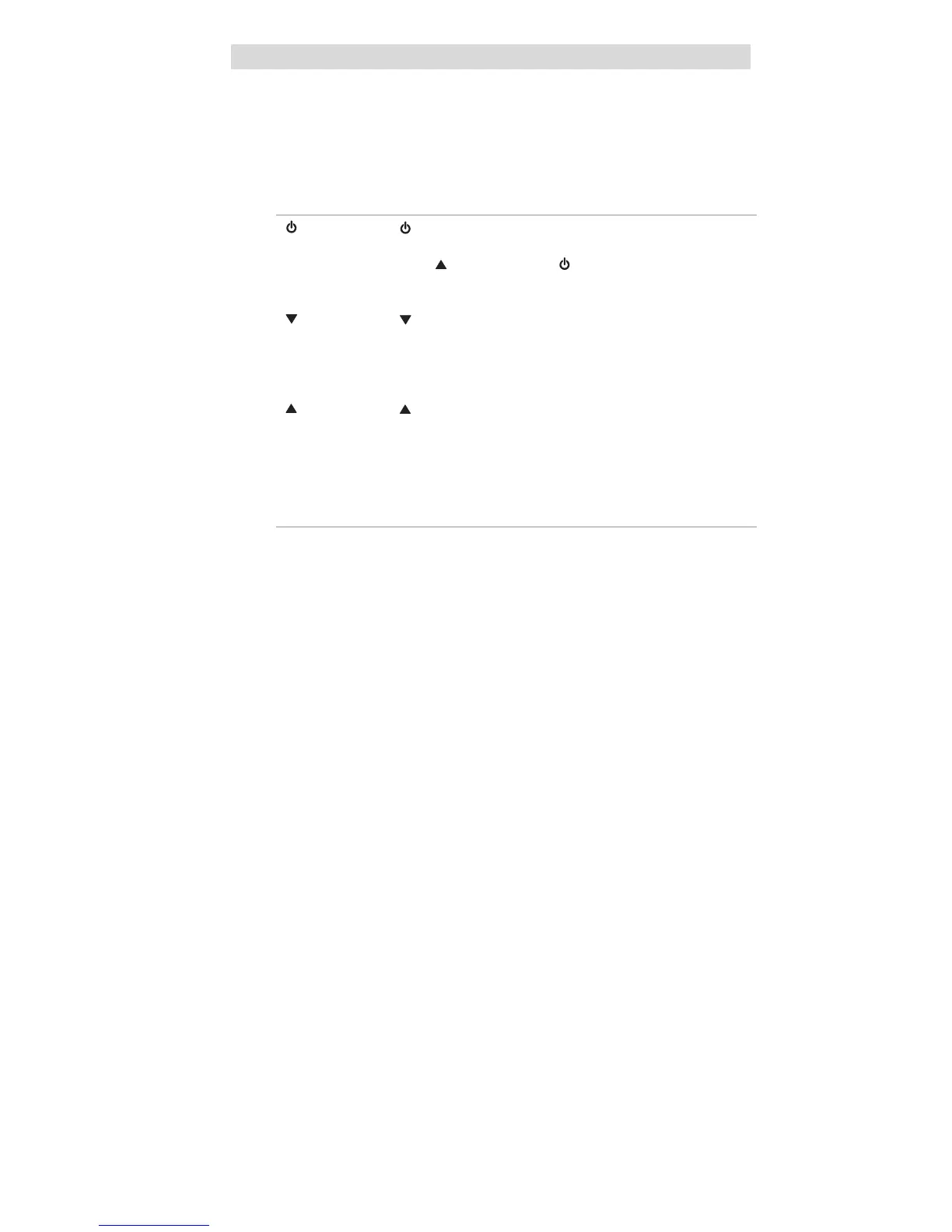
2.2.1 Button Definitions
Button Description
[
]
The
[
]
button is used to turn instrument ON or OFF and to
confirm user action selections.
When the
[
]
button and the
[
]
button are pressed
simultaneously at instrument start-up, the Options Setup
Mode displays.
[
]
The
[
]
button is used to move forward through data
screens in measuring mode, or as page back and to decrease
the values in set-up mode. Holding this button for 3 seconds
while in Normal Measure Mode will activate the
InstantAlert
TM
alarm.
[
]
The
[
]
button is used to reset peak, STEL TWA and
acknowledge alarms (where possible) or access calibration in
measuring mode. It is also used as page up or to increase the
values in set-up mode.
2.2.2 LED Definitions
LED Description
GREEN The Safe LED flashes once every 15 seconds to notify the
user that the instrument is ON and operating under the
conditions defined in section 3.7.
This option can be turned OFF through the MSA Link
software.
RED The red LEDs are visual indications of an alarm condition or
any type of error in the instrument.
2.2.3 Vibrating Alarm
The instrument is equipped with a vibrating alarm.
2.2.4 Backlight
The backlight automatically activates when any button is pressed. The
backlight remains ON for the duration of the user-selected timeout. This
ON/OFF duration can be set through MSA Link software.
2.2.5 Horn
The horn provides an audible alarm.