System Description 23
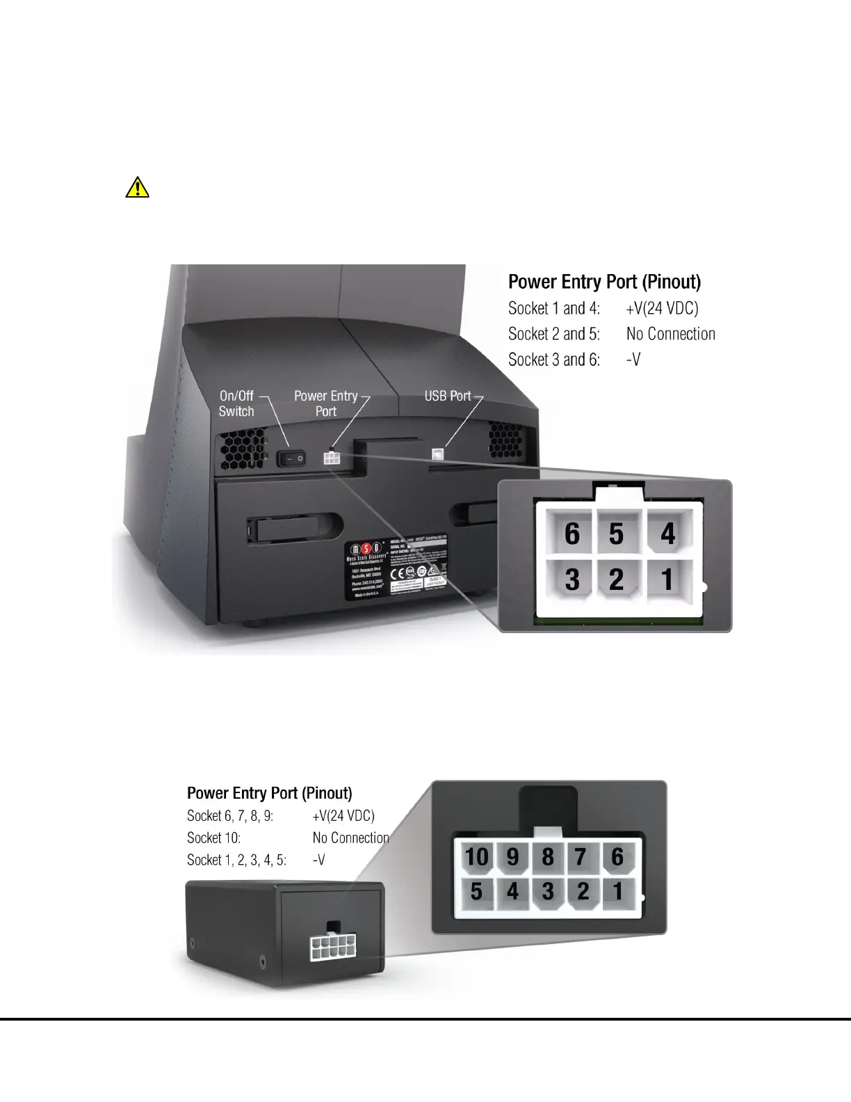
3.5.6 Power Switch and Input/Output (I/O) Panel
The on/off switch, power entry port, and a USB port for communication between the instrument and notebook computer are located on
the back of the instrument. Typically, the instrument should be left powered-on to maintain camera temperature.
WARNING: Only use cables and accessories supplied with the instrument. Use of cables and accessories other than those
supplied may degrade instrument performance and cause an electrical hazard.
Figure 3:6 Power switch, power entry port, and USB port on the back of the instrument
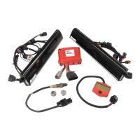
The power supply cannot be plugged directly into the imager. The system is supplied with an electrical noise filter, which protects the
system from electrical noise. Connect the 10-pin connector from the power supply into the electrical noise filter’s power entry port
(
Figure 3:7). Use the 6-pin power cord to connect the electrical noise filter to the power entry port on the back of the imager (Figure
3:6).
Figure 3:7 Electrical Noise Filter