2-10
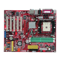
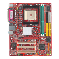
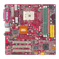
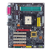
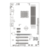
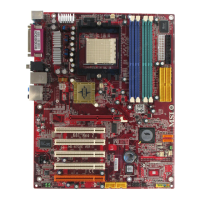
MS-6702E ATX Mainboard
Power Supply
The mainboard supports ATX power supply for the power system. Before inserting
the power supply connector, always make sure that all components are installed
properly to ensure that no damage will be caused.
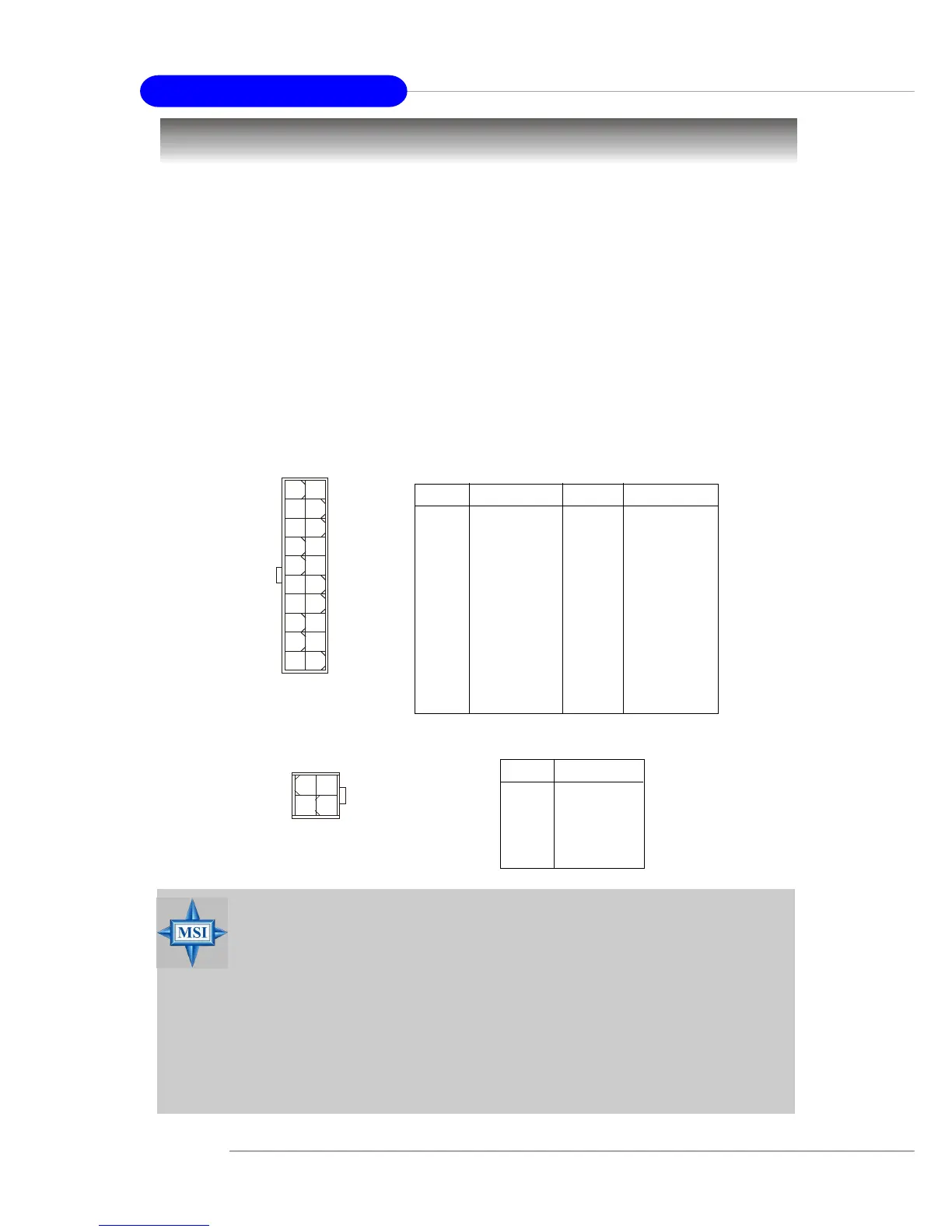
ATX 20-Pin Power Connector: JWR1
This connector allows you to connect to an ATX power supply. To connect to the ATX
power supply, make sure the plug of the power supply is inserted in the proper
orientation and the pins are aligned. Then push down the power supply firmly into the
connector.
ATX 12V Power Connector: JPW1
This 12V power connector is used to provide power to the CPU.
PIN SIGNAL
11 3.3V
12 -12V
13 GND
14 PS_ON
15 GND
16 GND
17 GND
18 -5V
19 5V
20 5V
PIN SIGNAL
1 3.3V
2 3.3V
3 GND
45V
5 GND
65V
7 GND
8 PW_OK
9 5V_SB
10 12V
JWR1 Pin Definition
PIN SIGNAL
1 GND
2 GND
3 12V
4 12V
JPW1 Pin Definition
JPW1
13
42
MSI Reminds You...
1. These two connectors connect to the ATX power supply and have to
work together to ensure stable operation of the mainboard.
2. Power supply of 300 watts (or above) is highly recommended for
system stability.
3. The system will be automatically shut down and secured when CPU
overheating occurred, so that you won’t be able to restart the sys-
tem at this situation. To release the security, please press and hold
the POWER button up to 4 seconds or disconnect the power cable
from the AC outlet, and then restart the system.
JWR1
10
1
20
11
 Loading...