450 Series Tillers
22
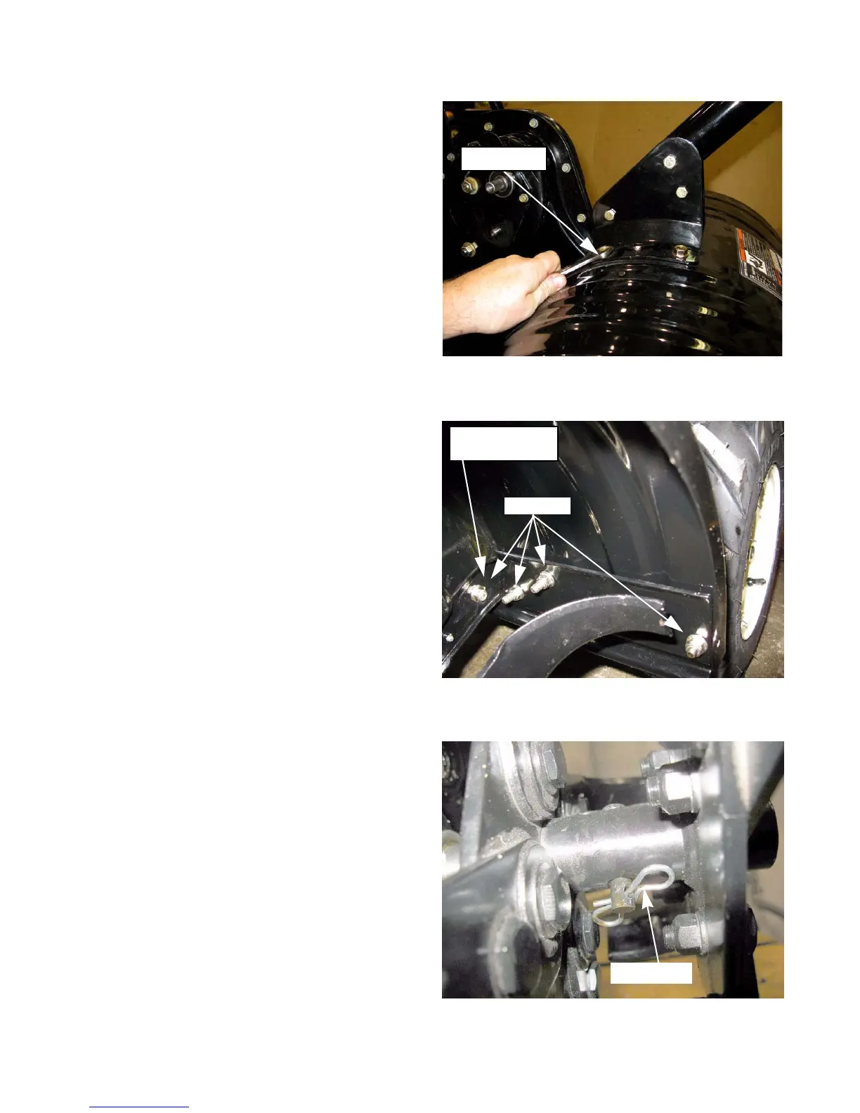
17. Remove both hex cap screws and flange lock nuts
from each side of the handle bracket by using a1/2"
and 9/16” wrench. See Figure 4.9.
NOTE: The 1/2” wrench is used on the top of the
tine cover and the 9/16” wrench is used on
the bottom of the tine cover.
18. Remove the handle assembly from the unit.
19. Remove the three hex cap screws and nuts that hold
the tine shield spacer bracket to the tine shield from
each side of the tine shield. See Figure 4.10.
20. Remove the center hex cap screw and nut from the
middle that added support to the tine shield spacer
bracket
21. Lift the tine Shield off of the tiller
22. Remove the clevis pins and bow tie clips securing
the right and left tine assemblies.
23. Remove both tine assemblies from the tine shaft
assembly.
NOTE: Make certain the tine shaft is lubricated prior
to re-assembly.
.
Figure 4.9
1/2” wrench
Figure 4.10
Remove
Center Support
Screw
Figure 4.11
Bow tie clip
For Parts Call 606-678-9623 or 606-561-4983
www.mymowerparts.com
 Loading...