QPS Evaluation Services Inc
Testing, Certification and Field Evaluation Body
Accredited in Canada, the USA, and Internationally
81 Kelfield St., Units 7-9, Toronto, ON M9W 5A3 Tel: 416-241-8857; Fax: 416-241-0682
www.qps.ca
QSD 34 Rev 04
Annex:
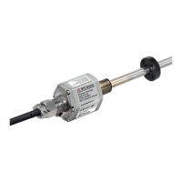
Product: Linear Position Sensors Tempsonics ® E-Series ET
Models: SSI Output, Analog & Digital Start/Stop
Ex tc IIIC T130°C Dc IP66/68
-40°C ≤Ta≤85°C
Class I/II/III Div 2 T4 ABCDFG
Class I Zone 2 T4 IIC
Zone 22 AEx tc T4 IIIC Dc
Ex tc IIIC T130°C Dc IP66/68
-40°C ≤Ta≤105°C
Class I/II/III Div 2 T4 ABCDFG
Class I Zone 2 T4 IIC
Zone 22 AEx tc T4 IIIC Dc
Ex tc IIIC T130°C Dc IP66/68
-40°C ≤Ta≤90°C
Class I/II/III Div 2 T4 ABCDFG
Class I Zone 2 T4 IIC
Zone 22 AEx tc T4 IIIC Dc
*Models are differentiated by output signal type
Each model has its own designated ambient range and dust temperature limitation (see table).
The sensors are supplied with a permanently connected cable with a rated voltage of 24 (-15%, +20%) VDC and
a maximum current of 105 mA.
The equipment is intended for permanent field installation.
Model nomenclature below:

 Loading...