4. Connections
4.1.1 Temposonics II Position Sensors with DPM or RPM
Table 4-A Connections - Temposonics II Position Sensor
MK292 Wire Color Wire Color Function Function
Connections Pin No. (Striped Leads) (Solid Leads) w/PWM Output w/Start/Stop Output
C32 1 White/Blue Stripe White DC Ground DC Ground
C32 2 Blue/White Stripe Brown Frame Frame
C28 3 White/Orange Stripe Gray (-) Gate Out (-) Start/Stop Pulse
C27 4 Orange/White Stripe Pink (+) Gate Out (+) Start/Stop Pulse
C30 5 White/Green Stripe Red + 15 Vdc + 15 Vdc
C31 6 Green/White Stripe Blue - 15 Vdc - 15 Vdc
No Connection 7 White/Brown Stripe Black Not Used Not Used
No Connection 8 Brown/White Stripe Violet Not Used Not Used
C24 9 White/Gray Stripe Yellow (+) Interrogation (+) Interrogation
C25 10 Gray/White Stripe Green (-) Interrogation (-) Interrogation
NOTE:
Verify if the cable has striped or solid color leads and make connections accordingly.
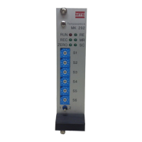
Figure 4-1
10 Pin 'RB' Style Connector
(Mating Connector: P/N 400755-3)
4.1.2 SE-based Temposonics LP Position Sensors with Start/Stop Output
Table 4-B Connections - SE-based Temposonics LP Position Sensor
MK292 Sensor
Connections Pin No. Wire Color Function
C28 1 Blue Gate (-)
C27 2 Green Gate (+)
C25 3 Yellow Interrogation (-)
C24 4 Orange Interrogation (+)
C30 5 Red Power, provided by MK292 (+15, ± 10%)
C32 6 Black Ground
No Connection 7 Drain Shield Drain Wire
No Connection 8 N/A N/A
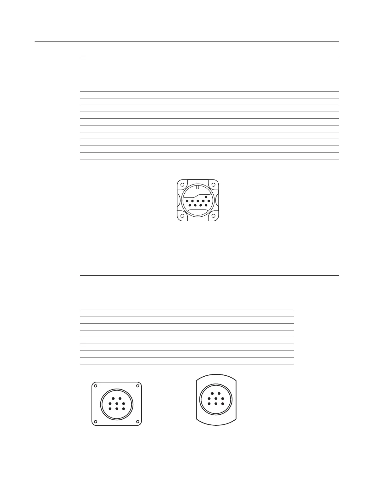
Figure 4-2a Figure 4-2b
Integral Connector Hanging Connector
Connection Type C, Connection Type H or J,
External View External View