4.3 Functional Inputs/Outputs
OUTPUTS:
Voltage Level: TTL level to 24 Vdc
Maximum Current Load: 20 mA (high level)
INPUTS:
Control Signal Level: ≥ applied Vin level
Current Load per Input: < 1 mA
4.3.1 Error Output (Loss of Feedback)
Pin: c5
Logic: HIGH: No Error; LOW: Error
Figure 4-7 Error Outputs
Errors:
• No sensor magnet
• Sensor magnet not positioned within the active range of sensor
• Malfunction or failure of sensor or module
• Electronic interference
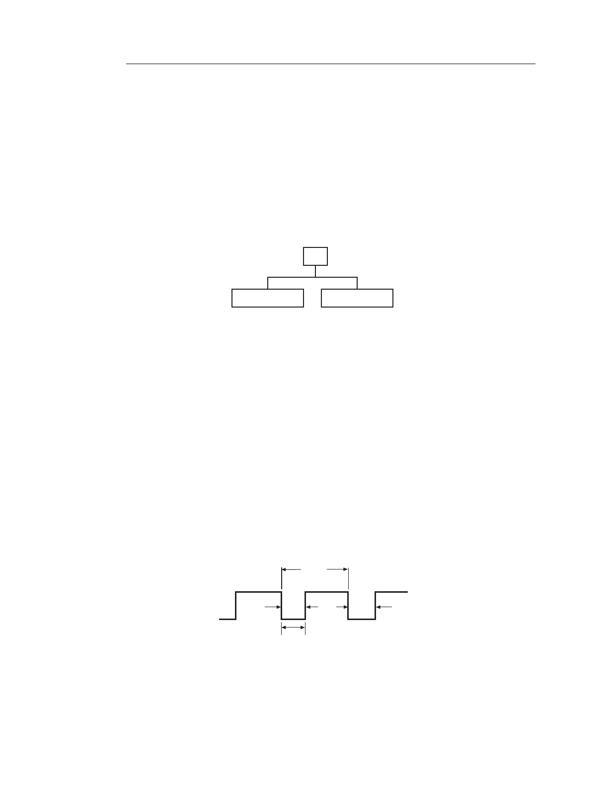
4.3.2 Data-Ready Output (Latch Pulse)
Pin: c6
Logic: HIGH
Ensures that parallel data transfer does not occur during data update
(i.e., during change in magnet position). In addition, the data ready
output confirms that the data is up-to-date.
The timing of data transfer is illustrated below.
Figure 4-8 Data Ready