Hold the programming switch in Position #2 until the 'RE' LED is lighted (≈ 3 sec.)
SETUP
The MK292 is now ready to accept the next parameter – Resolution (RE).
7.4 (RE) Resolution / Green LED
The resolution that can be achieved by the MK292 is dependent on the input from the
Temposonics position sensor. The chart below indicates the range of resolutions
depending on sensor type. Note that sensors with PWM output must be set for the
appropriate number of circulations to achieve desired output resolution.
RESOLUTION
Start/Stop Output
Range: 0.1 in. to 0.002 in. or 2.54 mm to 0.05 mm
PWM Output
Range: 0.1 in. to 0.0002 in. or 2.54 mm to 0.005 mm
(Note: Refer to Resolution vs. Circulation Chart, page 16)
1) Hold the programming switch in Position #2 until the 'RE' LED begins to flash (≈ 3 sec.)
ADJUST 2) Enter the desired resolution using BCD switches S1 - S6.
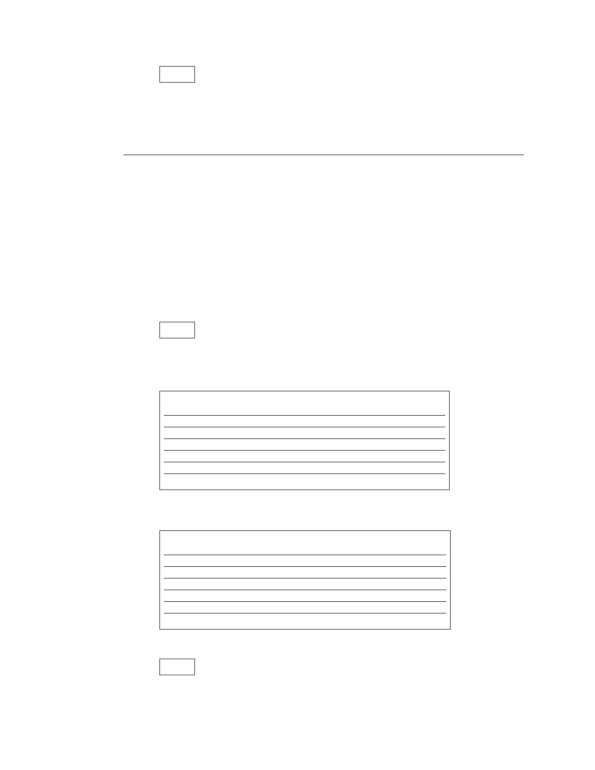
Table 7A
Table 7B
Hold the programming switch in Position #2 until the 'MR' LED begins to flash (≈ 3 sec.)
SETUP
The MK292 is now ready to accept the next parameter – Measuring Range (MR)
RE
SWITCH SETTINGS / RESOLUTION IN MILLIMETERS
Switches 0.005 mm 0.01 mm 0.05 mm 0.1 mm 0.5 mm 1.0 mm
S1 (0.00X) 5 0 0 0 0 0
S2 (0.0X) 0 1 5 0 0 0
S3 (0.X) 0 0 0 1 5 0
S4 (X.0) 0 0 0 0 0 1
S5 0 0 0 0 0 0
S6 0 0 0 0 0 0
SWITCH SETTINGS / RESOLUTION IN INCHES
Switches 0.0002 in. 0.0004 in. 0.002 in. 0.004 in. 0.02 in. 0.039 in.
S1 (0.000X) 2 4 0 0 0 0
S2 (0.00X) 0 0 2 4 0 9
S3 (0.0X) 0 0 0 0 2 3
S4 (0.X) 0 0 0 0 0 0
S5 0 0 0 0 0 0
S6 0 0 0 0 0 0
RE
SC
18