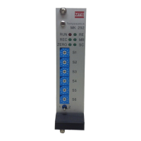
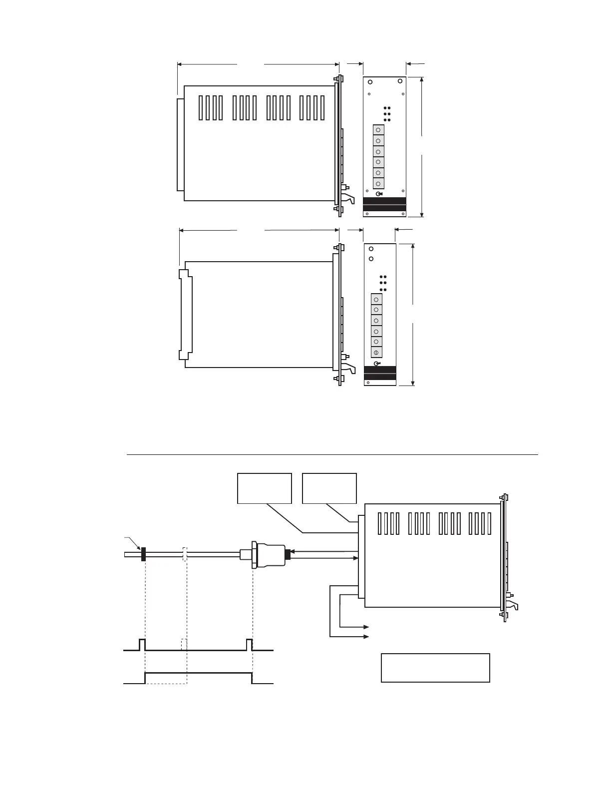
EasyManua.ls Logo

MTS Systems MK292 - System Configuration

MTS Systems MK292
30 pages
Print Icon
To Next Page IconTo Next Page
To Previous Page IconTo Previous Page
Loading...
Figure 1-2
MK292 Digital Output Module Dimensions
1.1 System Configuration
Figure 1-3
Typical System Configuration
MK292
Module
Magnet
Temposonics Sensor with
Start/Stop or PWM Output
Start/Stop Output
Max. Resolution: 0.002 in. (0.05 mm)
PWM Output
Max. Resolution: 0.0002 in. (0.005 mm)
24 Vdc
Power Suppy
Required
5 Vdc
Required for
TTL Output
Selectable: BCD, Binary, or Gray Code Displacement Output
Optional Voltage Output (0 to 10 Vdc or 10 to 0 Vdc)
for recording purposes only
NOTE:
BCD outputs are limited to a maximum
stroke length of 99.99 inches (2540 mm)
R
E
M
RUN
REC
ZER
l
MK 292
S
S
S
S
S
S
R
E
M
RUN
REC
ZER
l
MK 292
S
S
S
S
S
S
1.19 in.
30.2 mm
1.98 in.
50.4 mm
MK 292
Module
MK 292
Card
6.7 in.
170 mm
6.7 in.
170 mm
5.06 in.
128.4 mm
5.06 in.
128.4 mm
2