5. System Parameters
After the MK292 Digital Output Module is installed and connected to the Temposonics position sensor,
system parameters must be set before start-up. When setting the system parameters, you must be
aware which electronics module is installed in the Temposonics position sensor. Verify that the sensor
has either a start/stop or PWM output. If the sensor has a PWM output, also verify that it is config-
ured for external interrogation. Contact an MTS Applications Engineer if you have any questions
regarding the configuration of your sensor or how to interface to the MK292 unit.
The system parameters for each configuration are indicated below:
SYSTEM PARAMETERS SYSTEM PARAMETERS
(Sensor with PWM Outputs) (Sensor with Start/Stop Outputs)
< <
< <
NOTE:
Pulse Duration (REC) only applies to systems that are using sensors with a PWM output.
< <
< <
< <
< <
System parameters are set via the front panel of the MK292 using the programming and BCD switches.
• Programming Switch
This momentary toggle switch is located at the bottom of the front panel. It has two activation posi-
tions: #1 and #2. Programming Modes are accessed by manipulation of this switch as defined in the
Programming section of this manual.
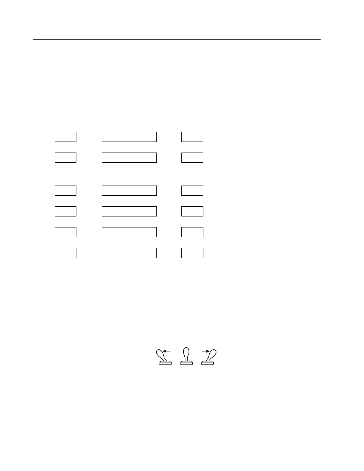
Figure 5-1
Programming Switch Positions
When the Programming Switch is pushed into either Position #1 or Position #2 it will automatically
return to the center (normal) position when released.