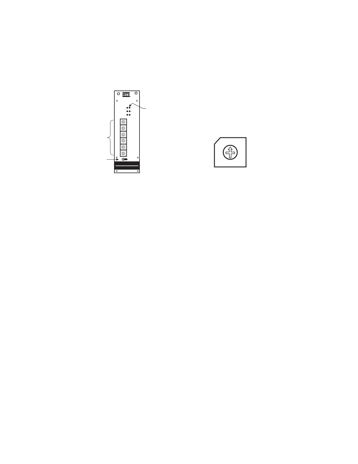
• BCD Switches (S1-S6)
The six rotary switches, S1 (least significant digit) to S6 (most significant digit), are used to set parame-
ter values. A screw driver or adjusting tool is used to set the switches.
The input values are checked against the actual values as indicated by the customer provided con-
troller display.
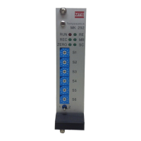
• LEDs
There are six LEDs, one red and five green, which give visual indication of the operating condition and
programming mode of the MK292.
1. RED (continuous light) = System in operation mode
2. RED (flashing light) = Transition to programming mode
3. GREEN (continuous light) = Indication of selected parameter
4. GREEN (flashing light) = Programming mode is activated – parameter settings can be
changed via BCD switches S1-S6.
5. GREEN (fast flashing light) = Input error
Figure 5-3
BCD Switch
Figure 5-2
Front Panel of MK292 Module