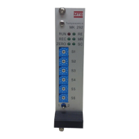
7.5 (MR) Measuring Range / Green LED
The measuring range or "stroke length" of the sensor must be set accurately to opti-
mize the interdependence of the other parameters. This value is indicated on the sen-
sor label as "stroke" and will be in either inches or millimeters.
1) Hold the programming switch in Position #2 until the 'MR' LED begins to flash (≈ 3 sec.)
ADJUST 2) Enter the measuring range using BCD switches S1 - S6.
Example:
Update Time Formula:
Tud = [(Lm + 120 mm) (13) (N)] ÷ 36
Where:
Update Time (in milliseconds) = Tud
Length in mm = Lm
Circulation Count = N
1) Hold the programming switch in Position #2 until the 'ZERO' LED begins to flash (≈ 3 sec.)
SETUP
The MK292 is now ready to accept the next parameter -- Null Adjust (ZERO).
MR
NOTE:
When the measuring range is set, the measuring fre-
quency and system update time is also set. Refer to the
tables below to see the relationship of measuring
range, frequency, and update time.
MILLIMETERS
Measuring Range: 1525 millimeters
Switch (mm) Setting
S1 (1.0) 5
S2 (10) 2
S3 (100) 5
S4 (1000) 1
S5 (n/a) 0
S6 (n/a) 0
INCHES
Measuring Range: 120.5 inches
Switch (in.) Setting
S1 (0.1) 5
S2 (1.0) 0
S3 (10) 2
S4 (100) 1
S5 (n/a) 0
S6 (n/a) 0
MR
NOTE:
Pin c14 of the MK292 permits you to select the unit of
measurement (i.e., inches or millimeters) and must be
wired accordingly (refer to section 4.2).
19
NOTE:
When using inches, use the following
formula to convert inches to millimeters:
Inches x 25.4