4.1.3 Temposonics L Series Position Sensors with Start/Stop Output
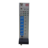
Table 4-C.1 Connections - Temposonics L Series Position Sensor with RG Connector
MK292
Connection Pin No. Wire Color Function
C28 1 Gray (-) Gate
C27 2 Pink (+) Gate
C24 3 Yellow (+) Interrogation
C25 4 Green (-) Interrogation
C2 5 Red or Brown Power supplied by MK292 (+ 24 Vdc)
C32 6 White DC Ground
7 - No Connection
Figure 4-3
RG Connector
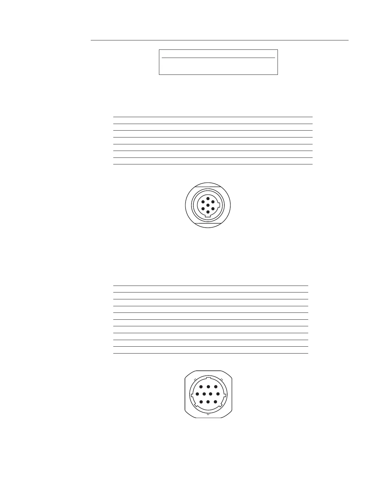
Table 4-C.2 Connections - Temposonics L Series Position Sensor with MS Connector
MK292
Connection Pin No. Wire Color Function
C32 A White DC Ground
B - No Connection
C28 C Gray (-) Gate
C27 D Pink (+) Gate
C2 E Red Power supplied by MK292 (+ 24 Vdc)
F - No Connection
G - No Connection
H - No Connection
C24 J Yellow (+) Interrogation
C25 K Green (-) Interrogation
Figure 4-4
MS Connector
(Mating Connector: P/N 370013)
CAUTION!
When wiring Temposonics L Series sensors, DO NOT
connect DC ground to the cable shield or drain wire.
7