Table 4-C.3 Connections - Temposonics L Series Position Sensor with RB Connector
MK292
Connection Pin No. Wire Color Function
C32 1 White DC Ground
2 - No Connection
C28 3 Gray (-) Gate
C27 4 Pink (+) Gate
C2 5 Red Power supplied by MK292 (+ 24 Vdc)
6 - No Connection
7 - No Connection
8 - No Connection
C24 9 Yellow (+) Interrogation
C25 10 Green (-) Interrogation
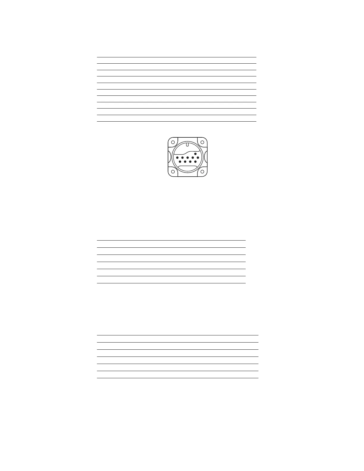
Figure 4-5
RB Connector
(Mating Connector: P/N 400755-3)
Table 4-C.4 Connections - Temposonics L Series Position Sensor with RO Integral Cable
MK292
Connection Wire Color Function
C28 Gray (-) Gate
C27 Pink (+) Gate
C24 Yellow (+) Interrogation
C25 Green (-) Interrogation
C2 Red or Brown Power supplied by MK292 (+ 24 Vdc)
C32 White DC Ground
Table 4-C.5 Connections - Temposonics L Series Position Sensor with HO Integral Cable*
MK292
Connection Wire Color Function
C28 White (-) Gate
C27 Black twisted w/white (+) Gate
C24 Blue (+) Interrogation
C25 Black twisted w/blue (-) Interrogation
C2 Red Power supplied by MK292 (+ 24 Vdc)
C32 Black twisted w/red DC Ground
*The HO Integral Cable [maximum length 30 feet (9.14 m)] was not available at the time
this manual was printed. Please contact the factory for status.