8.5.2 Valve protrusion – Measurement
Preconditions
☑ Engine is stopped and starting disabled.
Special tools, Material, Spare parts
Designation / Use Part No. Qty.
Depth gage, 200 mm
Y20000918 1
Preparatory steps
1. Remove cylinder-head cover upper section (→ Page 94).
2. Remove injector (→ Page 97).
3. Install barring tool (→ Page 75).
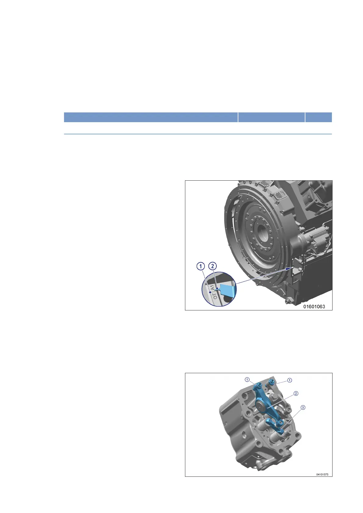
4. Turn crankshaft in direction of engine rota-
tion using barring tool until OT marking (1)
and pointer (2) are aligned.
Measuring valve protrusion
1. Check TDC position of piston in cylinder A1:
• If rocker arms on cylinder A1 are unloaded, the piston is in firing TDC.
• If rocker arms on cylinder A1 are loaded, the piston is in overlap TDC.
2. Measure valve protrusion for each valve in two crankshaft positions (firing TDC and overlap TDC) according
to the diagram. Diagram (→ Page 90).
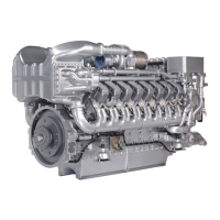
3. Undo adjusting screw (1) and remove valve
bridge (3). Do not remove rocker arm (2).
88 | Valve Drive | MS150049/04E 2017-04
TIM-ID: 0000070354 - 001