Diagram for 20V engines – two
crankshaft positions
Checking valve clearance at two crankshaft positions
1. Check TDC position of piston in cylinder A1:
• If rocker arms on cylinder A1 are unloaded, the piston is in firing TDC.
• If rocker arms on cylinder A1 are loaded, the piston is in overlap TDC.
2. Check valve clearance adjustment with cold engine:
• Inlet valves (long rocker arm) = ±0.05 mm
• Exhaust valves (short rocker arm) = ±0.05 mm
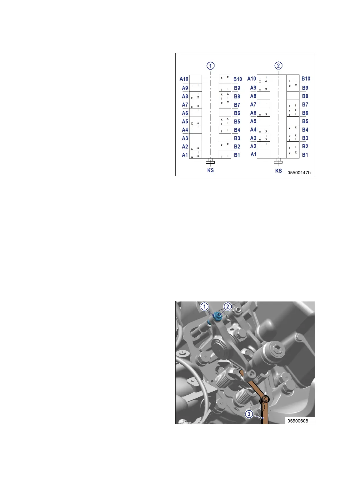
3. Check all valve clearances in two crankshaft positions (firing TDC and overlap TDC of cylinder A1) as per
diagram:
1 Cylinder A1 is in firing TDC
2 Cylinder A1 is in overlap TDC
I Inlet valve
X Exhaust valve
4. Use feeler gage to determine the distance between valve bridge and rocker arm.
5. If the deviation from the set value exceeds ±0.05 mm, adjust valve clearance.
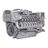
Adjusting valve clearance
1. Release locknut (1).
2. Insert feeler gage (3) between valve bridge
and rocker arm.
3. Use Allen key to set adjusting screw (2) so
that the specified valve clearance is estab-
lished.
4. Feeler gage (3) must just pass through the
gap.
92 | Valve Drive | MS150049/04E 2017-04
TIM-ID: 0000004357 - 008