7.22.6 Engine control unit – Removal and installation
Preconditions
☑ Engine is stopped and starting disabled.
Special tools, Material, Spare parts
Designation / Use Part No. Qty.
Connector pliers
0135315483 1
Covering caps for Cannon sockets
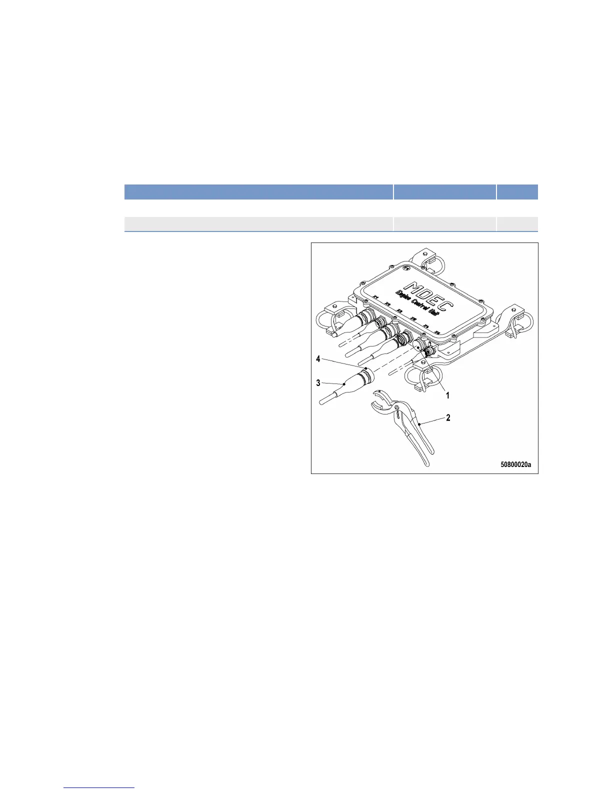
Removing control unit from engine
1. Note or mark assignment of cables to con‐
nector sockets.
2. Use connector pliers (2) to disengage the
bayonet union nuts (4) of the connectors (3)
by turning them counterclockwise.
3. Remove all connectors.
4. Close connector sockets with appropriate
covering caps (1).
240 | Task Description | MW15550/06E 2012-02
TIM-ID: 0000008487 - 004
 Loading...