Home
Mueller
Controller
SENTRY II
Mueller SENTRY II Installation Operation & Maintenance
4
of 1
of 1 rating
69 pages
Give review
Manual
Specs
To Next Page
To Next Page
To Previous Page
To Previous Page
Loading...
Sentry II with W
ater
W
orks Box Operating Instructions
Effectiv
e April 1, 2000
P
ar
t No
.
8823728
Revised No
vember 10, 2003
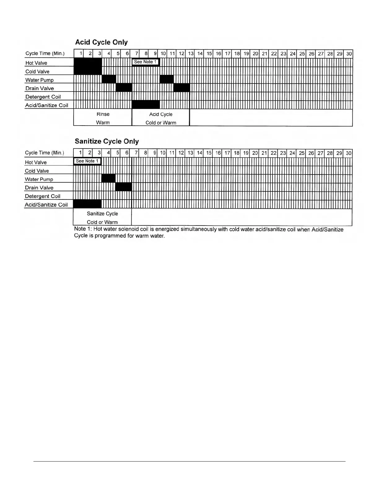
Char
t 2 - Acid Cycle or Sanitize Cycle
NOTE:
Fill and drain times are charted with the PLC potentiometer turned to the far counterclockwise
position. See Section 5.3 and Figure 26.
35
38
40
Table of Contents
Default Chapter
2
Table of Contents
2
Section 1.0 - Introduction
5
General
5
Technical Support
5
Regulatory Requirements
5
Figure 1 - Sentry II Control Cabinet and Milk Cooler Components
6
Section 2.0 - Installation
7
Crate Removal
7
Skid Removal
7
Site Requirements
8
Hot Water Requirements
8
Water Supply Pressure
8
Electrical Requirements
8
Foundation Requirements
9
Formula 1-Gross Weight of Milk Cooler
9
Leveling the Milk Cooler
10
Bulk Head Installations
11
Milk Room Installations
12
Agitator Assembly Installation
13
Pump Assembly and Electric Drain Installation
14
Instructions for Mounting the Sentry II Control Box Enclosures
15
Water Line Connections
15
Chemical and Cleaning Cautions
16
Manway Wash Tube Installation
17
Spray Dish Installation
18
Milk Cooler Vent Assembly Installation
19
Section 3.0 - Electrical Wiring
20
Field Electrical Connections at Milk Cooler's Rear Junction Box
20
Figure 15—Electrical Schematic - Rear Junction Box
21
Figure 16—Internal Conduit Raceways - Milk Cooler
22
Figure 17—Electrical Schematic - Field Wiring (Enlarged Schematic Attached in Back)
23
Figure 18—Electrical Schematic - Factory Wiring (Enlarged Schematic Attached in Back)
24
Figure 19—Relay and Switch Contact Positions (for Sentry II with Water Works Box)
25
Section 3.0 - Electrical Wiring - Continued
26
PLC Electrical Troubleshooting (Input and Output Data)
26
Figure 20—Electrical Schematic - PLC (for Sentry II Models with Water Works Box)
27
Figure 21—Electrical Schematic - Water Works Box
28
Section 4.0 - Sentry II Temperature Control
29
Sentry II Temperature Control and Thermocouple Sensor
29
Sentry II Thermocouple Sensor Installation
29
Sentry II Thermocouple Sensor Wiring
30
Important Thermocouple Splicing Information
31
Sentry II Temperature Control Calibration Accuracy
31
Figure 24—Sentry II Thermocouple - Temperature Control Wiring
31
Sentry II Temperature Control Lock and Unlock Features
32
Sentry II Temperature Control Calibration
32
Sentry II Temperature Control Set Point Adjustment
33
Sentry II Temperature Control Unit of Measure (Fahrenheit or Celsius)
34
Section 5.0 - Chemical Dosing with Sentr y II Water Works Box
35
Determining Chemical Usage
35
Chemical Cautions (Additional Cautions Are Listed in Section 2.15)
35
Determining Water Usage Requirements
36
Determining Actual Water Usage
37
Table 2—Minimum Water Requirements (Per Cycle)
37
Wash Cycle Timing Sequence
38
Chart 1-Detergent Wash or Complete Wash
38
Chart 2-Acid Cycle or Sanitize Cycle
39
Section 6.0 - Sentry II PLC Programming
40
Sentry II Programmable Features, Options, and Recommendations
40
Sentry II - MTA to PLC Programming Procedures
41
Sentry II Service Reference Form, Programmable Features
50
Section 7.0 - Operating Instructions
51
General
51
Cool-Off-Wash Rotary Selector Switch
51
Cooling Bottom Units Switch
51
Cooling All Units Switch
52
Pre-Start Cooling Switch
52
Pre-Start Agitator Switch
52
Section 7.0 - Operating Instructions - Continued
53
Detergent Cycle Switch
53
Acid Cycle Switch
53
Sanitize Cycle Switch
53
Agitate Sample Switch
53
Alarm Lamp
54
Milk Temperature Display
54
Cooling Override Switch (Emergency Use Only)
54
Section 8.0 - Weights and Dimensions
55
English Weights and Dimensions
55
Metric Weights and Dimensions
56
Section 9.0 - Sentry II Equipment Markings
57
Label No. 8822229, Lock out
57
Label No. 8820482, Caution - Disconnect Power and Retain Latch
57
Label No. 8820623, Warning Symbol - Electrical
57
Label No. 8805616, Manual - Run Position
57
Label No. 8820248, Auto - Automatic Run Position
57
Label No. 8822584, Pump Motor - Wire Marker
57
Label No. 8802375, Agitator(S) - Wire Marker
57
Label No. 3791, Hot - Water Valve Marker
58
Label No. 3792, Cold - Water Valve Marker
58
Label No. 8823612, Warning - Water Works Box
58
Label No. 8823013, Warning - Disconnect Power before Servicing
58
Label No. 8822225, CE Data Tag (U.K. Models Only)
58
Label No. 8801150, Warning - Disconnect Power before Servicing
59
Label No. 8820410, Data Tag (U.K. Models Only)
59
Label No. 30612, Notice - Chart Accuracy
59
Label No. 8820454, Dry Nitrogen Holding Charge
60
Label No. 8805299, Warning - HCFC Class II Refrigerant
60
Label No. 30737, Bottom Temp-Plate
60
Label No. 8822972, Transformer Wiring
61
Label No. 8822705, Canadian and U.S. Certification
61
Label No. 8823729, 24 VAC and 240 VAC Component List
61
Label No. 8820409, Mueller Name Tag
61
Label No. 8823369, Programmable Controller Name Tag
62
Label No. 8822558, Mueller Milk Cooler Data Tag
62
Label No. 30890, Mueller Data Tag - Control Box
62
Label No. 8820677, Ground Symbol
62
Label No. 30397, Stainless Steel Symbol
62
Label No. 30166, Caution - Vent Must be over Milk Inlet
63
Label No. 8802777, Caution - Do Not Sanitize
63
Label No. 8823146, Terminal Block - 24 VAC - 240 VAC
63
Section 10.0 - Safety
64
General
64
Manway
64
Section 11.0 - Disposal
65
General
65
Chemical Disposal
65
Solid Component Disposal
65
Other manuals for Mueller SENTRY II
Installation And Operation Manual
83 pages
4
Based on 1 rating
Ask a question
Give review
Questions and Answers:
Need help?
Do you have a question about the Mueller SENTRY II and is the answer not in the manual?
Ask a question
Mueller SENTRY II Specifications
General
Brand
Mueller
Model
SENTRY II
Category
Controller
Language
English
Related product manuals
ISOBUS SPRAYER-Controller MAXI 3.0
110 pages
ISOBUS SPRAYER-Controller MIDI 3.0
110 pages

 Loading...