EasyManuals Logo

Mueller SENTRY II Installation Operation & Maintenance

Mueller SENTRY II
69 pages
To Next Page IconTo Next Page
To Previous Page IconTo Previous Page
Page #6 background imageLoading...
Page #6 background image
Sentry II with Water Works Box Operating Instructions Effective April 1, 2000
Part No. 8823728 Revised November 10, 2003
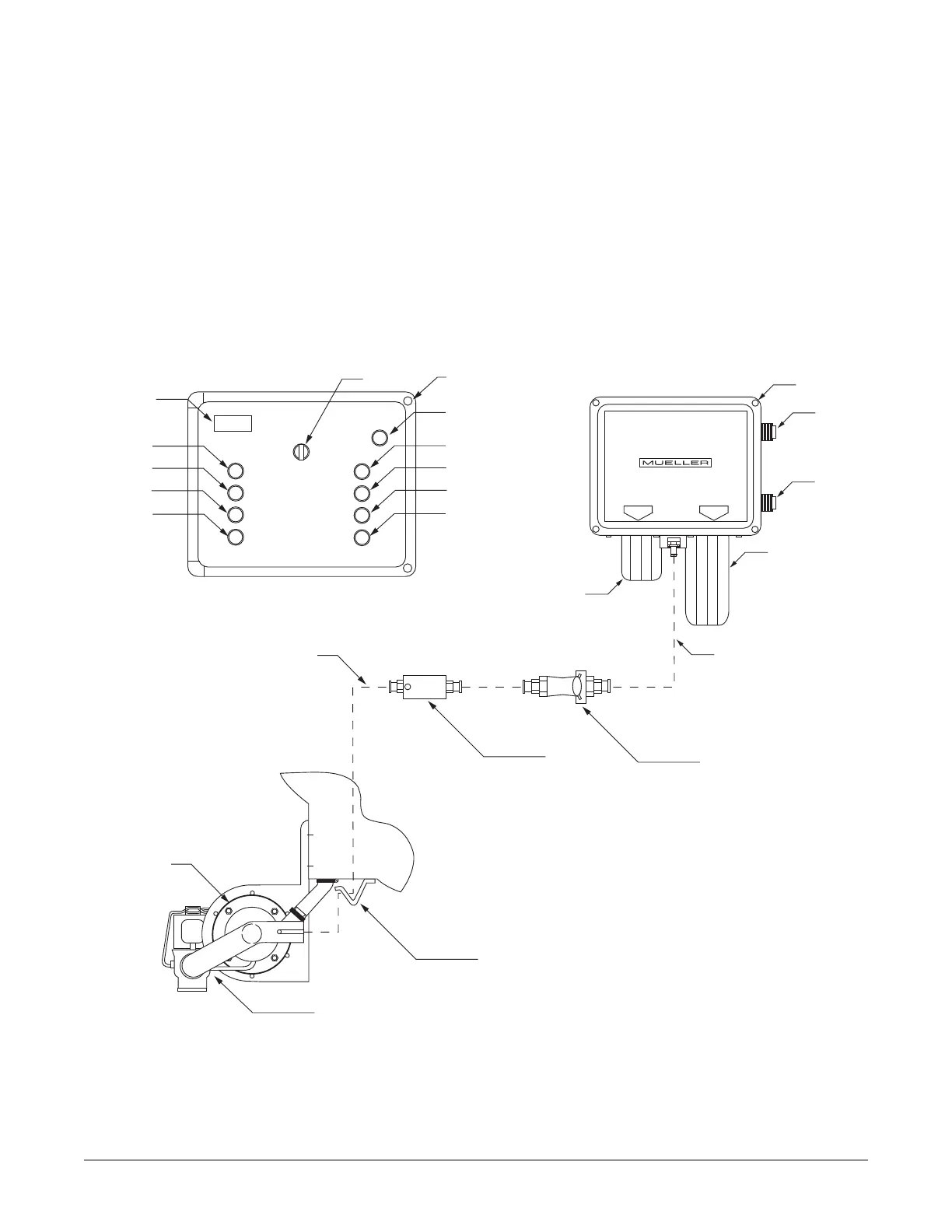
Figure 1 - Sentry II Control Cabinet and Milk Cooler Components
2
A. Sentry II Control Box
B. Alarm Indicator
C. Detergent Switch/Indicator
D. Acid Switch/Indicator
E. Sanitize Switch/Indicator
F. Sample Agitation Switch/Indicator
G. Cool/Off/Wash Selector Switch
H. Digital Temperature Indicator
I. Cooling Switch/Indicator (Bottom Units)
J. Cooling Switch/Indicator (All Units)
K. Pre-Start Switch/Indicator (Cooling)
L. Pre-Start Switch/Indicator (Agitate)
M. Water Works Box
N. Hot Water Solenoid
O. Cold Water Solenoid
P. Detergent Jar
Q. Acid/Sanitize Jar
R. Fill Line Disconnect -
3
/
8
" x
5
/
8
"
S. Flow Control Orifice
T. Wash Pump Assembly
U. Electric Drain Valve
V. External Trough - Raceway
R
S
3
/8" ID Hose
5
/8" Water/Chemical
Fill Line to Milk Cooler
A
WASH
M LK TEMPERATURE
ALARM
OFF
COOL
COOLING BOTTOM UNITS
COOLING ALL UNITS
PRE START COOL NG
PRE START AG TATOR
DETERGENT CYCLE
AC D CYCLE
SANITIZE CYCLE
AGITATE SAMPLE
B
C
D
E
F
G
H
I
J
K
L
ACID
SAN T ZER
DETERGENT
Q
P
O
N
M
V
T
U

Table of Contents

Other manuals for Mueller SENTRY II

Questions and Answers:

Question and Answer IconNeed help?

Do you have a question about the Mueller SENTRY II and is the answer not in the manual?

Mueller SENTRY II Specifications

General IconGeneral
BrandMueller
ModelSENTRY II
CategoryController
LanguageEnglish

Related product manuals