Self-moving multipurpose loader MULTIONE
1 Series
Instruction manual (Traslation of original instructions)
CM170001EN - 01.03.17 - 03 (11.07.18)
17/49
MultiOne SRL
DESCRIPTION OF THE MACHINE -4
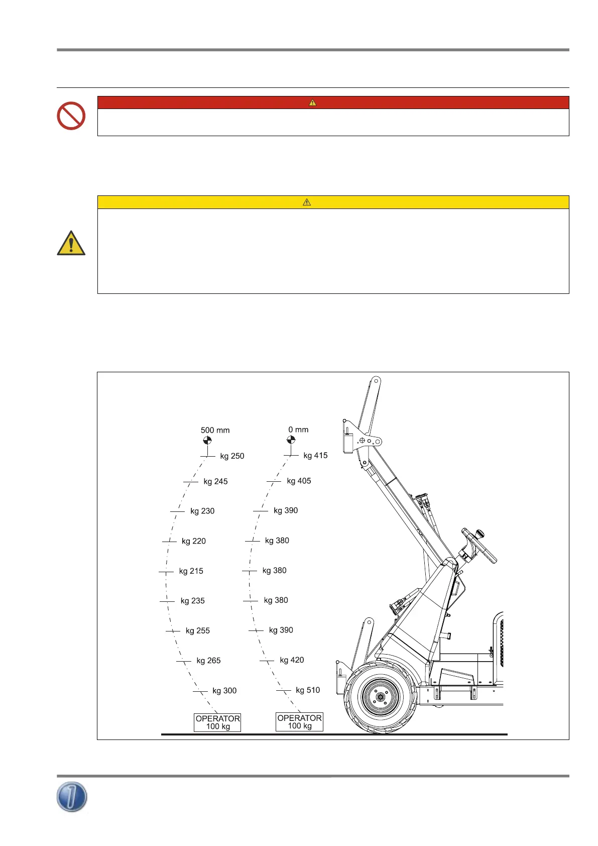
4.7 Load diagram
DANGER
IT IS FORBIDDEN TO EXCEED THE LOAD CAPACITY OF THE MACHINE (SEE FIG. 5).
The load diagram shown in FIG. 5 is obtained in accordance with standard ISO 14397-1:2007, and shows the load capacity of the
machine in the different position of the lifting boom.
The load diagrams are intended with the machine stopped in the position of maximum steering, placed on solid and flat surface,
with 100 kg operator in the driving seat and equipped with tyres Tractor model.
ATTENTION
MOVING THE LOAD BARYCENTRE DETERMINES THE CHANGE OF LIFTING CAPACITY OF THE MACHINE.
THE LIFTING CAPACITY INDICATED IS COMPREHENSIVE OF THE WEIGHT OF THE ACCESSORY USED, SO THE NET LIFTING
CAPACITY IS THE VALUE SHOWN IN THE GRAPHIC MINUS THE ACCESSORY WEIGHT.
WHEN WORKING ON UNEVEN OR SOFT GROUND WITH OBSTACLES IT IS COMPULSORY TO KEEP THE ATTACHMENT AS NEAR AS
POSSIBLE TO THE GROUND AND REDUCE THE LOAD UNDER THE MACHINE’S LIFTING CAPACITY. THIS WILL MAKE THE MACHINE
MORE STABLE.
The curves shown in the diagram represent the load capacity respectively (from left to right):
• curve n. 1, operator weighing 100 kg, seated in the driving seat and barycentre 0 mm;
• curve n. 2, operator weighing 100 kg, seated in the driving seat and barycentre 500 mm;
It can be noted that during the movement of the lifting boom the barycentre changes compared to the starting position and
consequently the load capacity of the machine varies.
FIG. 5
 Loading...