Addendum to
Operating and Maintenance Manual
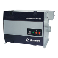
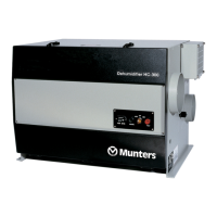
Model HC-300 Dehumidifier
Applies to HC-300 units beginning with serial number 7175
This section includes information which applies to HC-300 units which have had the pressure
differential switch installed. The information below applies to sections in the basic "Operating and
Maintenance Manual - Model HC-300 Dehumidifier". The new or revised information is printed in
italics.
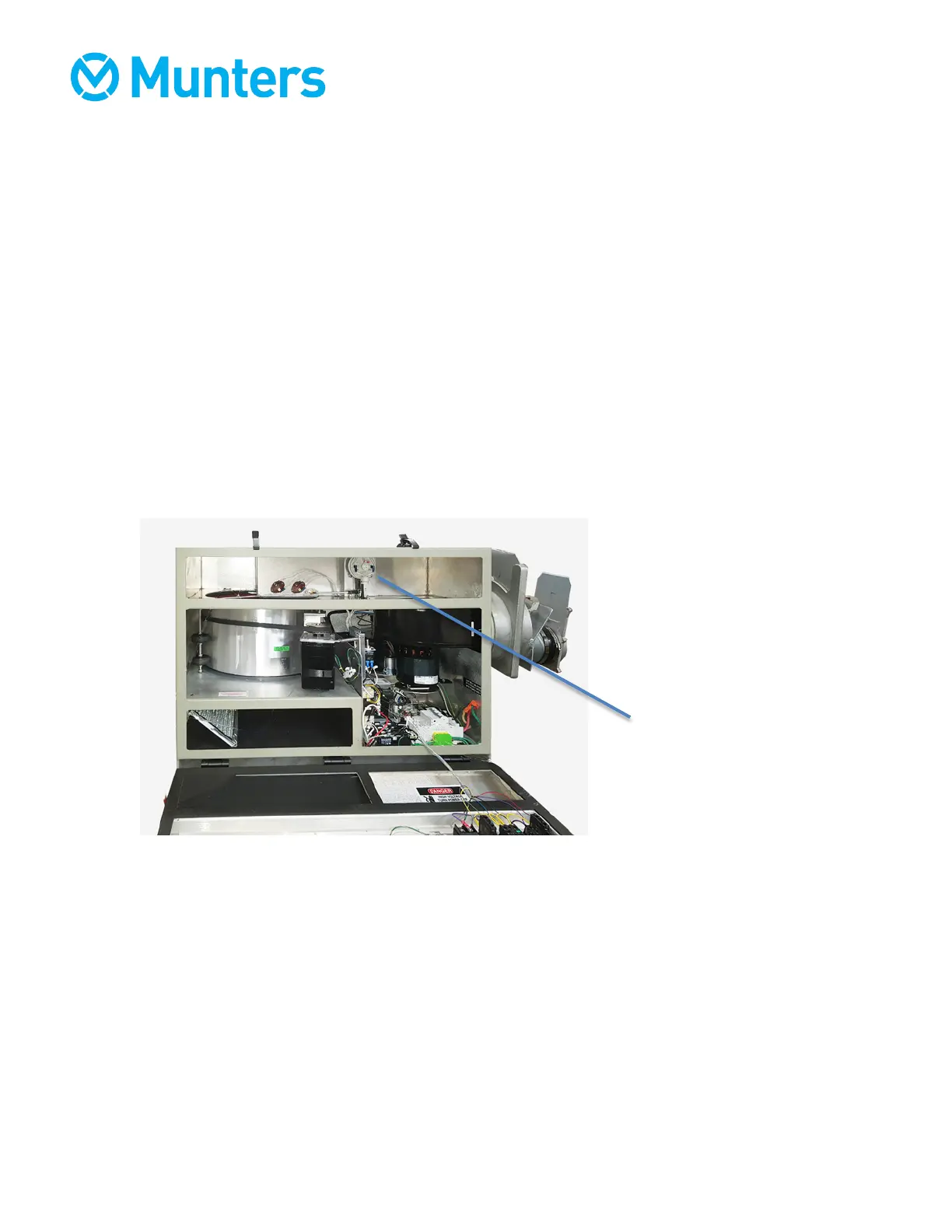
These versions of the HC-300 include a pressure differential switch to detect minimum
reactivation air flow. If the air flow drops below the factory specification, the electric heater will be
disengaged. The pressure differential switch is mounted near the rear of the upper section of the
unit, as shown below:
The pressure differential switch senses the pressure difference between the inlet and outlet of the
reactivation air stream, measured across the wheel. The switch has tubing connections to both
sides of the desiccant wheel in the reactivation zone.
• When operating conditions and air flows are normal, the pressure drop across the wheel is
above the setpoint for the flow switch. The contacts in the pressure differential switch are
closed, allowing the contactor to send power to the heating element as long as normal
conditions apply.
• If the flow of reactivation air is blocked or limited for some reason, the pressure differential
switch detects that the pressure difference across the wheel has dropped below the setpoint.
The contacts in the pressure differential switch open, opening the contactor and cutting off
power to the heating element.