Added to Section 1.2 - About the HC-300
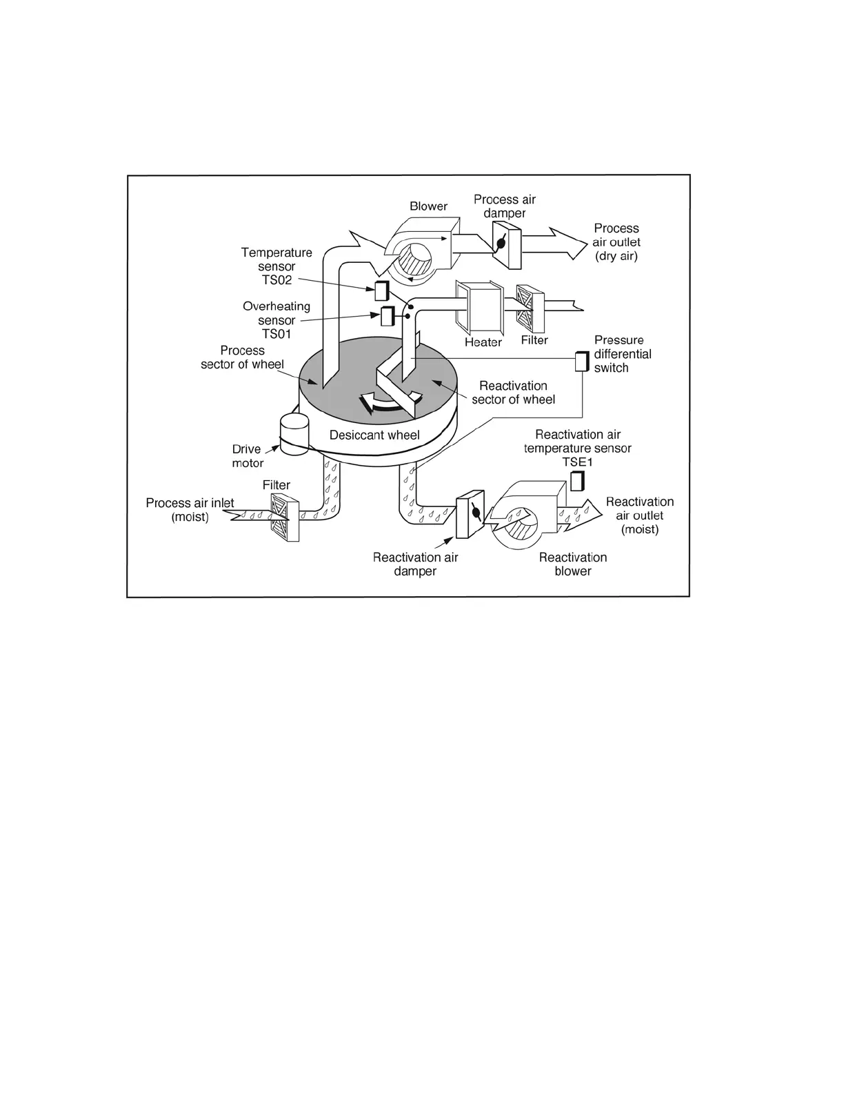
The following diagram shows how the pressure differential switch is arranged to measure the
pressure difference across the wheel.
FIGURE 1-2 - HC-300 IN OPERATION
Added to Section 3.6 - Adjusting the Dampers
Notes -
• In some installations, the conditions of the process air entering the unit will change frequently.
In a case like this, it may be necessary to leave the reactivation damper completely open.
This will prevent nuisance overheating faults.
• During setup, if the reactivation damper is closed too far, this may cause the pressure
differential switch to trip and turn off the heater. This will be indicated by a quick drop in the
reactivation outlet temperature.
• The setpoint for the pressure differential switch is set at the factory. The setpoint should not
be adjusted. Unauthorized changes to the setpoint may damage the HC-300 and/or void the
warranty.
Added to Section 5.5 - Poor Dehumidification Performance
• This can be caused by insufficient reactivation air flow. Limited reactivation air flow can
cause the pressure differential switch to disengage the heaters. Increased external static
pressure may have been introduced into the system. You may need to adjust the dampers or
decrease the reactivation external static pressure. See Section 3.6 - Adjusting the Dampers.
• The pressure differential switch may not have detected a low reactivation air flow before the
thermoswitch reacted. Check that the pressure differential switch is functional. The static
tubes for the pressure differential switch may be blocked.