EasyManuals Logo

Murr Elektronik Cube67+ User Manual

Murr Elektronik Cube67+
43 pages
To Next Page IconTo Next Page
To Previous Page IconTo Previous Page
Page #14 background imageLoading...
Page #14 background image
Manual Cube67+ | System Manual
14
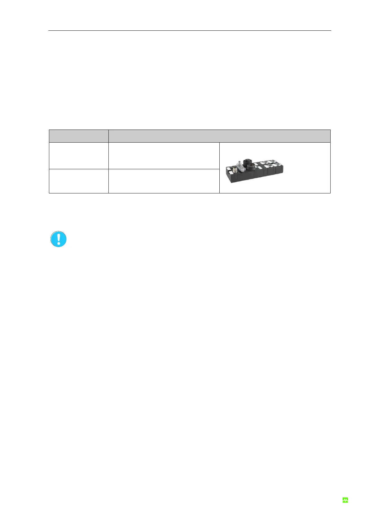
3.1.2 Cube67+ Bus Node
The bus node connects the I/O modules to the fieldbus. It is supplied via a 7/8" power cable and fea-
tures four connections for the internal system connection. A maximum of 10 I/O modules per segment
can be connected. This is a total of up to 20 I/O modules for one bus node. The I/O modules are sup-
plied via the internal system connection.
Article number
Description
56521
Cube67+ BN-P
56526
Cube67+ BN-PNIO
Tab. 1: Cube67+ Bus Node
For the exact connection diagram and settings please refer to the corresponding
product manuals.
You will find an overview on the manuals in the section "Manual Overview and Lay-
out" in this manual.

Questions and Answers:

Question and Answer IconNeed help?

Do you have a question about the Murr Elektronik Cube67+ and is the answer not in the manual?

Murr Elektronik Cube67+ Specifications

General IconGeneral
BrandMurr Elektronik
ModelCube67+
CategoryGateway
LanguageEnglish

Related product manuals