Do you have a question about the Murr Elektronik Cube67+ and is the answer not in the manual?
Explains symbols and icons used to denote important information and warnings.
Describes the intended application and usage environment for the products.
Defines the necessary qualifications and training for personnel handling the devices.
Lists the additional features and benefits of the Cube67+ system compared to Cube67.
Details the established advantages and benefits of the Cube67 system.
Provides instructions and references for mounting the system components.
Details the wiring and connection diagrams for the system.
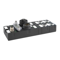
Describes the different components that make up the Cube67+ system.
Explains the coding system used to identify product components and their characteristics.
Details the Cube67+ bus node, its function, and connectivity.
Discusses the Cube67 modules and their operation with the Cube67+ bus node.
Describes the Cube67+ modules and their specific features and expansion capabilities.
Explains the internal system connection using hybrid cables and their purpose.
Details the use and specifications of 7/8" pre-wired power cables for the system.
Lists and describes various accessories available for the Cube67+ system.
Describes the Cube67 T-coupler M12 6 pole and its function.
Lists different types of blind plugs used for system connections and protection.
Details terminating resistors required for system connections to ensure signal integrity.
Information on labeling accessories for component identification.
Describes ground straps for proper grounding and interference reduction.
Overview of intelligent current monitoring types and their specifications for protection.
Warning about potential damage from inverting I/O modules and the importance of labeling.
Illustrates the system topology, showing the arrangement of components and connections.
Explains the requirement for terminal resistance and locking caps for IP67 protection.
Describes the division of the internal system connection into segments and lines.
Details the maximum expansion limits in terms of length and number of modules per segment.
Specifies the maximum number of modules that can be connected per bus node and segment.
Warning against using the power distributor to supply the bus node or green system line.
Provides essential notes for configuring the power supply for the system.
Lists recommended Murrelektronik power supply units for the system.
Explains how sensors are supplied with power and protection mechanisms.
Shows the derating diagram for normal sensor module operation at different temperatures.
Shows the derating diagram for I/O link modules at different temperatures.
Details the actuator supply for external components, noting current limits.
Explains the connection and supply of analog setting modules.
Covers actuator connection, maximum current draw, and polarity warnings.
Explains the function of the diagnostic input on digital modules and its configuration.
Provides examples of how to use the DESINA diagnostic function for fault indication.
Describes how to connect sensors/actuators with diagnostic output for fault localization.
Details cable break monitoring using an adapter for detecting wire breaks in M12 lines.
Outlines the necessary safety precautions for handling ESD-sensitive devices.
Explains the importance of proper grounding for interference voltage diversion.
Provides basic rules for cable routing to avoid EMC problems.
Discusses the impact of voltage drops on system operation and signal changes.
Recommends using separate power supplies for optimal EMC.
Explains integrated protective circuits for safety against interference from inductive loads.
Discusses additional measures and limits for meeting EMC requirements in various configurations.
Definition of actuator shutdown due to short-circuit or overload.
Definition of Analog Input.
Definition of Bus Node - Profibus.
Definition of a 16-bit identifier for Profibus products.
Details the limitations of liability for the technical documentation.
Outlines the copyright restrictions for the documentation.
Defines the terms and conditions for using the documentation.
| Model | Cube67+ |
|---|---|
| Power Supply | 24 V DC |
| Communication Protocol | EtherNet/IP |
| Operating Temperature | -25...+60 °C (depending on the model) |
| Housing Material | Plastic |
| Storage Temperature | -40...+70 °C |