Manual Cube67+ | System Manual
24
3.2.3 Segments and lines
The internal system connection is divided in 2 segments and, due to this division, is operable with
longer line lengths and a larger number of modules.
Sockets 0 and 2 belong to the left segment of the internal system connection; sockets 1 and 3 belong
to the right segment.
If modules are connected to an associated socket x, this is referred to as a connection to line x,
whereby x corresponds to the related socket number. For example, Line 0 for Socket 0, Line 1 for
Socket 1, etc.
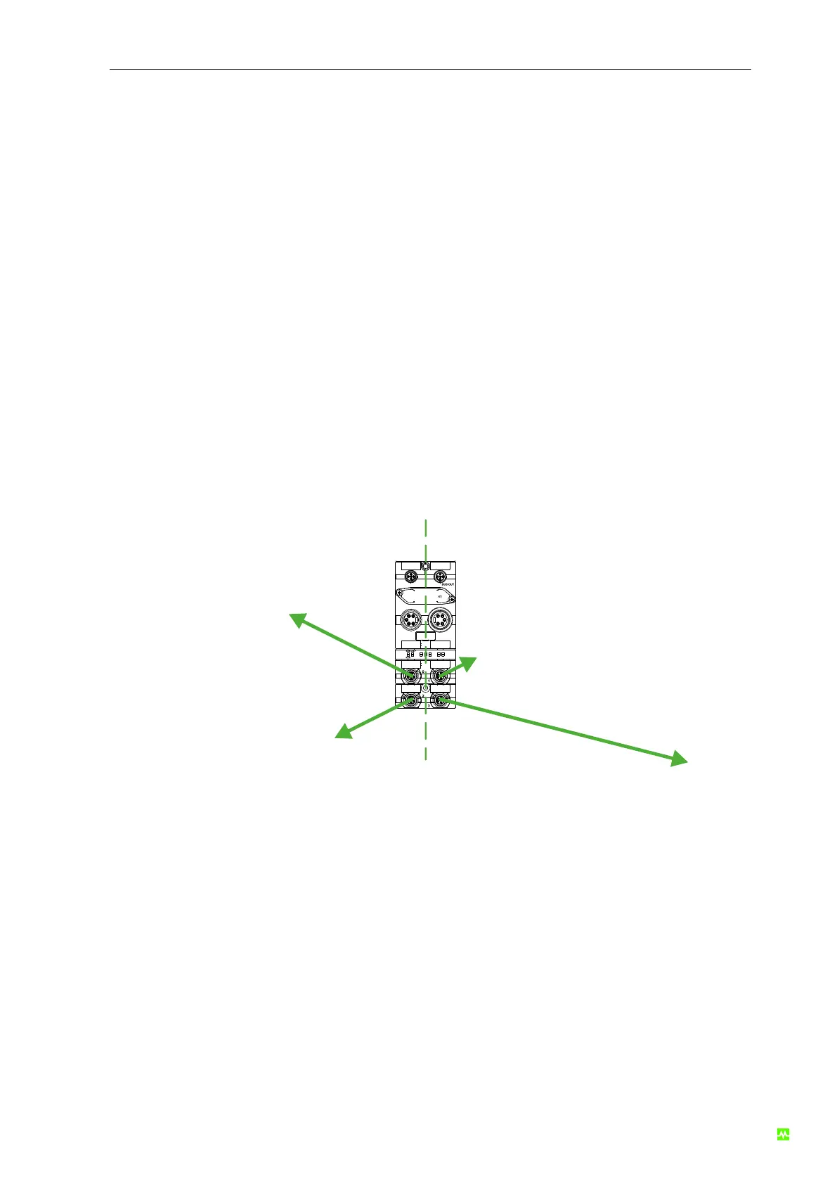
3.2.4 Maximum expansion
The maximum expansion per segment is 30 m. The lengths within the line are freely selectable, how-
ever, the sum per segment must not exceed 30 m!
The following illustrations shows an expansion example:
U
S
U
A
BUS IN
POWER IN POWER OUT
ADDRESS
×10
Segment1
(max. 30 m)
Segment2
(max. 30 m)
0 m
3
0
m
2
0
m
1
0
m
Fig. 6: Maximum expansion
3.2.5 Number of components
Max. 32 expansion modules per Cube67+ bus node are possible (16 per segment). The modules can
be connected to the segments in any arrangement, however, not more than 16 modules per segment.