EasyManuals Logo

Murr Elektronik Cube67+ User Manual

Murr Elektronik Cube67+
43 pages
To Next Page IconTo Next Page
To Previous Page IconTo Previous Page
Page #30 background imageLoading...
Page #30 background image
Manual Cube67+ | System Manual
30
3.4 Connecting Sensors and Actuators
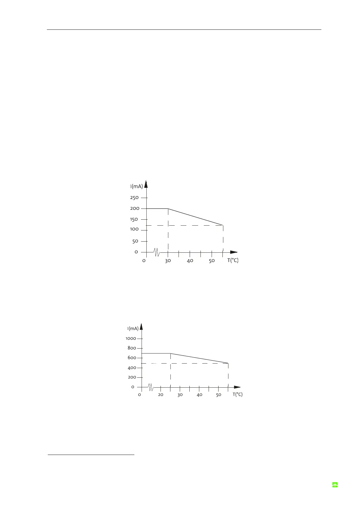
3.4.1 Sensor supply
Sensors can be supplied by
2
the I/O module. A re-settable PTC per M12 socket protects the sensor
supply. The maximum current draw for the sensor power supply is 200 mA and for I/O - slots 700 mA.
Please note the following derating diagram.
3.4.1.1 Derating of the sensor modules normal
Fig. 9: Derating of the sensor module normal
3.4.1.2 Derating of the I/O link modules
Fig. 10: Derating of the I/O link modules
2
This does not apply for art. nos. 56 710 / 56 720 / 56 740

Questions and Answers:

Question and Answer IconNeed help?

Do you have a question about the Murr Elektronik Cube67+ and is the answer not in the manual?

Murr Elektronik Cube67+ Specifications

General IconGeneral
BrandMurr Elektronik
ModelCube67+
CategoryGateway
LanguageEnglish

Related product manuals