Manual Cube67+ | System Manual
26
3.2.6 Load rating
The modules connected to the bus node are supplied with two voltages via the internal system con-
nection.
Module electronics and sensors
Tab. 11: Supply by the internal system connection
ATTENTION:
Make sure to avoid back discharge of the sensor supply voltage caused by external
supply of the Cube67+ system.
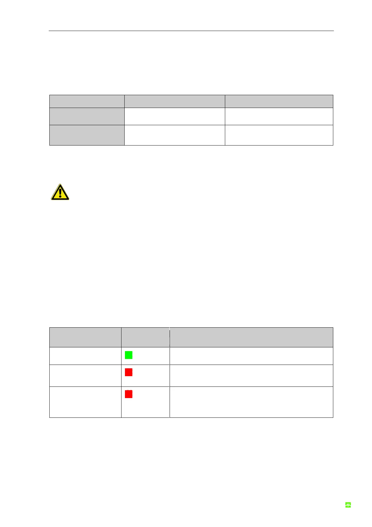
Protection
An intelligent current monitoring integrated into the bus node recognizes overload and short circuits. If
one of these states is recognized, the voltage at the affected line is shut down. When the failure is
resolved, the system is re-started by a Power ON reset.
Overload is activated, when the permissible current is exceeded by over 10%, that is I ≥ 4,4 A.
Between 4 A and 4.4 A, an overload diagnostic is generated on the fieldbus, however, the affected
voltage is not shut down.
Overload - Diagnostic, voltage at the affected line is shut
down.
Tab. 12: Overload or short circuits of the intelligent current monitoring