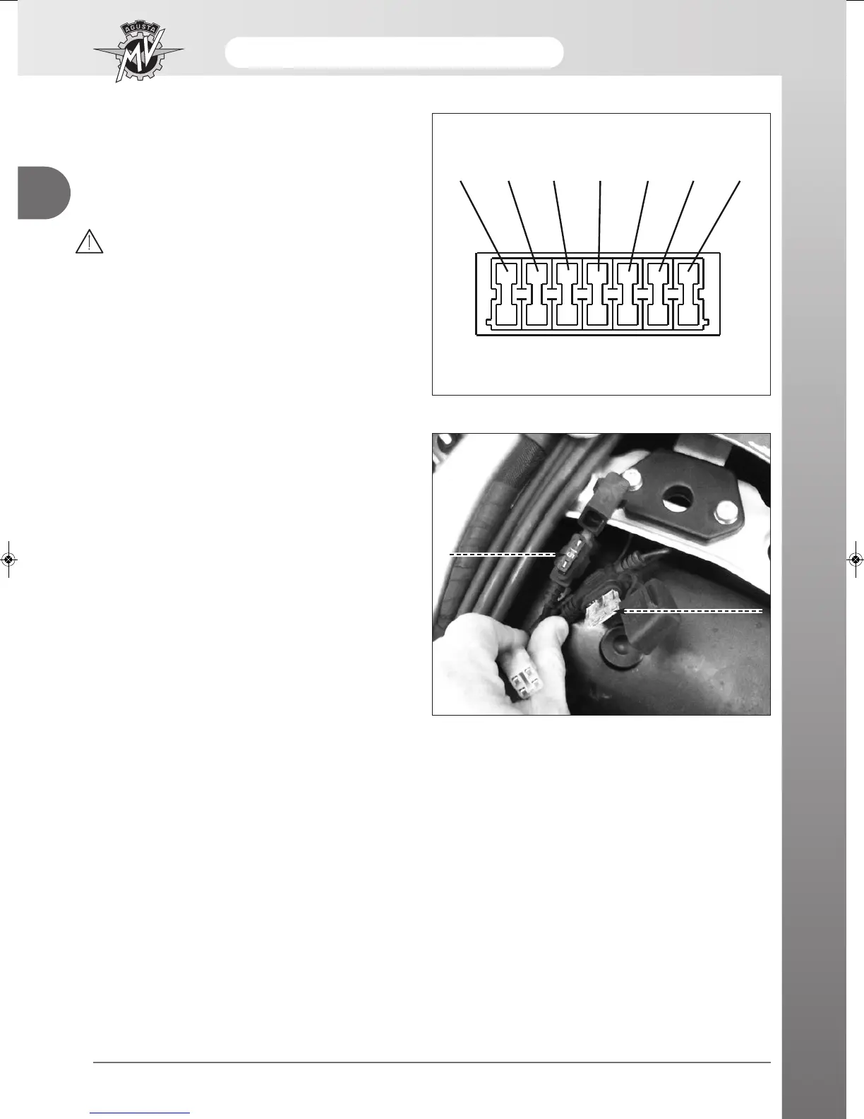
- To identify the position and function of the fuses, refer
to the information shown in the enclosed electrical
diagram. The reference letters in the figure corre-
spond to those shown in the diagram.
Remember that the tool bag contains three spare
fuses.
WARNING
Never replace a fuse with a rating other than
that precribed, in order to avoid damage to
the electrical equipment of the motorcycle
which could lead to a fire.
ABS Fuses - Replacement (MY13) *
- On F4 MY13 models equipped with ABS system, the
related fuses are placed under the rider’s saddle:
- No.1 fuse - 15A
- No.1 fuse - 25A (fuse holder marked with white
paint)
- Unfasten and lift the fuses caps.
- Replace the blown fuse and refit the caps.
(*): This function is present only on certain models
ABS fuse
(25A)
ABS fuse
(15A)





 To Next Page