- 42 -
Electrical system
E
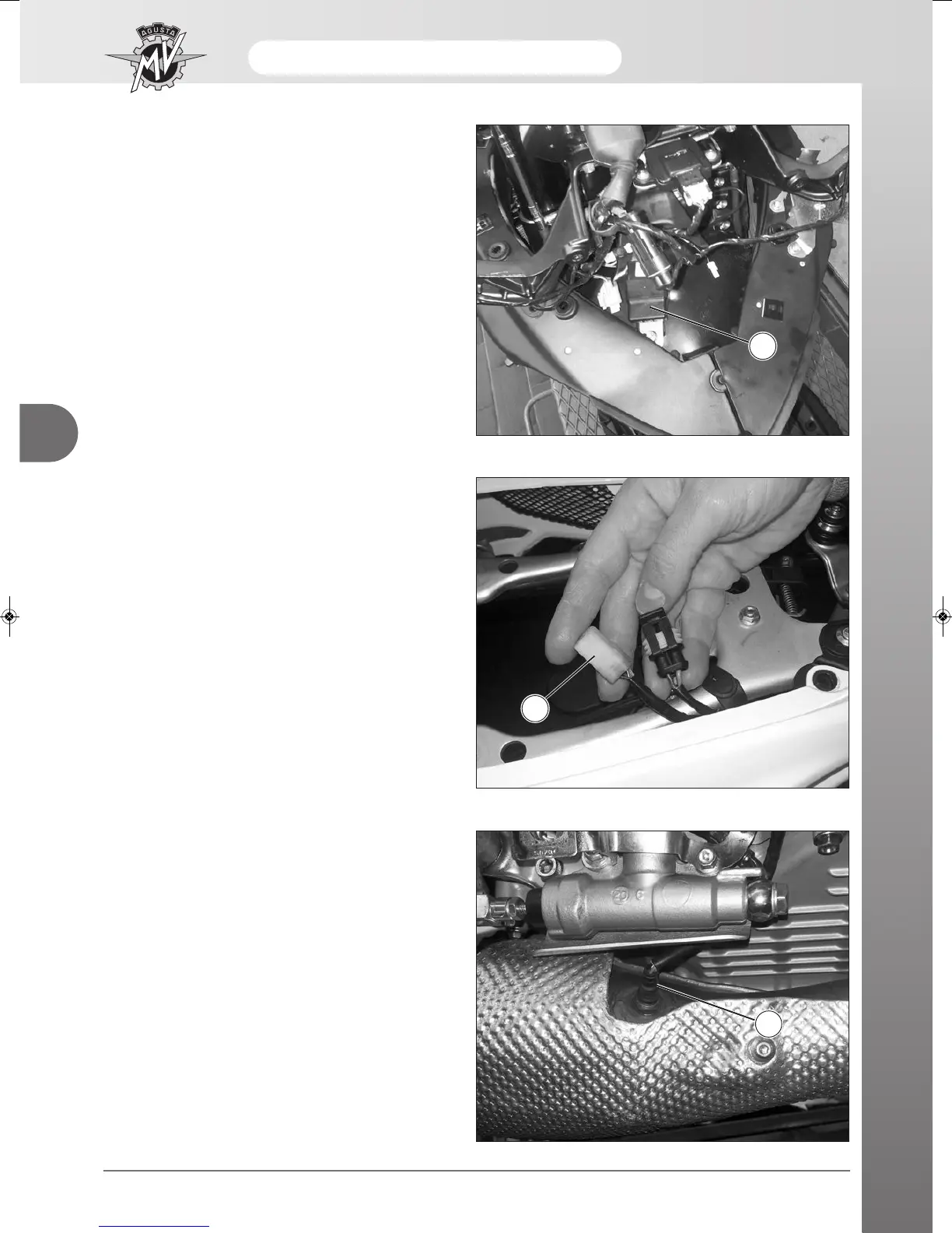
INTERMITTENCE RELAY
The intermittence relay (1) is placed on the front part of
the motorcycle, upon the central conveyor.
1
DIAGNOSTICS UNIT
The diagnostics connector (2) is placed under the pas-
senger’s saddle.
With the ignition key in OFF position, remove the pro-
tecting cap from the connector and connect it to the
diagnostics unit.
2
LAMBDA SENSOR
The lambda sensor (3) is placed on the right side of the
exhaust manifolds.
Its working is completely controlled by the ECU.
3