the battery with direct current of 0.6 A. During charg-
ing, the screw plugs must be unscrewed!
Charging must be continued until all cells uniformly
and briskly evolve gas and the desired voltage is read+
ed, i.e. about 2.5 to 2.7 Vlcell.
Two to three measurements taken at an interval of
one hour must show a constant electrolyte density
(1.28
f
0.01 g/cm3) and cell voltage. The specified cur-
rent of 0.6 A must be maintained at any rate.
During charging, the temperature of the electrolyte
must not exceed 50
"C.
Please notice!
Do not subject the battery to a rapid
charging process! As a consequence,
the battery will become useless bo-
fore long and you will lose the rig111
to raise guarantee claims.
Before connecting the battery to the vehicle,
connect
the tu.0 battery cables to the poles (red cable to thc
positive pole
-
bro\vn cable to the negative pole) and
apply a thin film of grcase for battery terminals
01.
acid-frec Vaseline to the poles.
After fitting the protective cap in place. the battery
can be installed and the two battery cables connected
to the
lower contact blades of the plug-type at the
fuse base
[(l)
in Fig.
93).
Again pay attention to the correct
way of connecting:
rcd cable to the red cable,
bro\vn cable to the brown cable.
The vent hose must be placed in such a way that acid
that may be spilled through this hose cannot damage
lacquered or other metal parts.
5.3.2. Servicing the Battery
The average life of a battery is about two years. This
time can be extended or shortened by good servicing
or by neglecting it. In the main, servicing operations
are restricted to the cleaning of the terminals
-
a thin
film of grease for battery terminals mu~t allVags be
applied
-
and the checking of the acid level at re
g
-
ular intervals (every four weeks during the warm
season of the year, every two weeks during the cold
season of the year).
When greasing the terminals take care that no grease
enters the cells. If the acid level has fallen below the
desired level, only top up with distilled water.
Do not use so-called improving agents!
..
If, nevertheless, acid is spilled from the battery, the
density of the acid used for topping up should be so
selected that the density of the complete amount of
acid in the battery in fully charged condition will be
1.28
f
0.01 g/cm3.
If the battery is not used or if less than 50 km are cov-
ered daily, the battery must be re-charged once every
month.
5.4.
Ignition System
5.4.1. Ignition Coil
The ignition coil may be compared with
a
transformer
which transforms a low voltage into a high one. As
only an alternating current can be transformed, the
vehicle electrical system is supplied with direct cur-
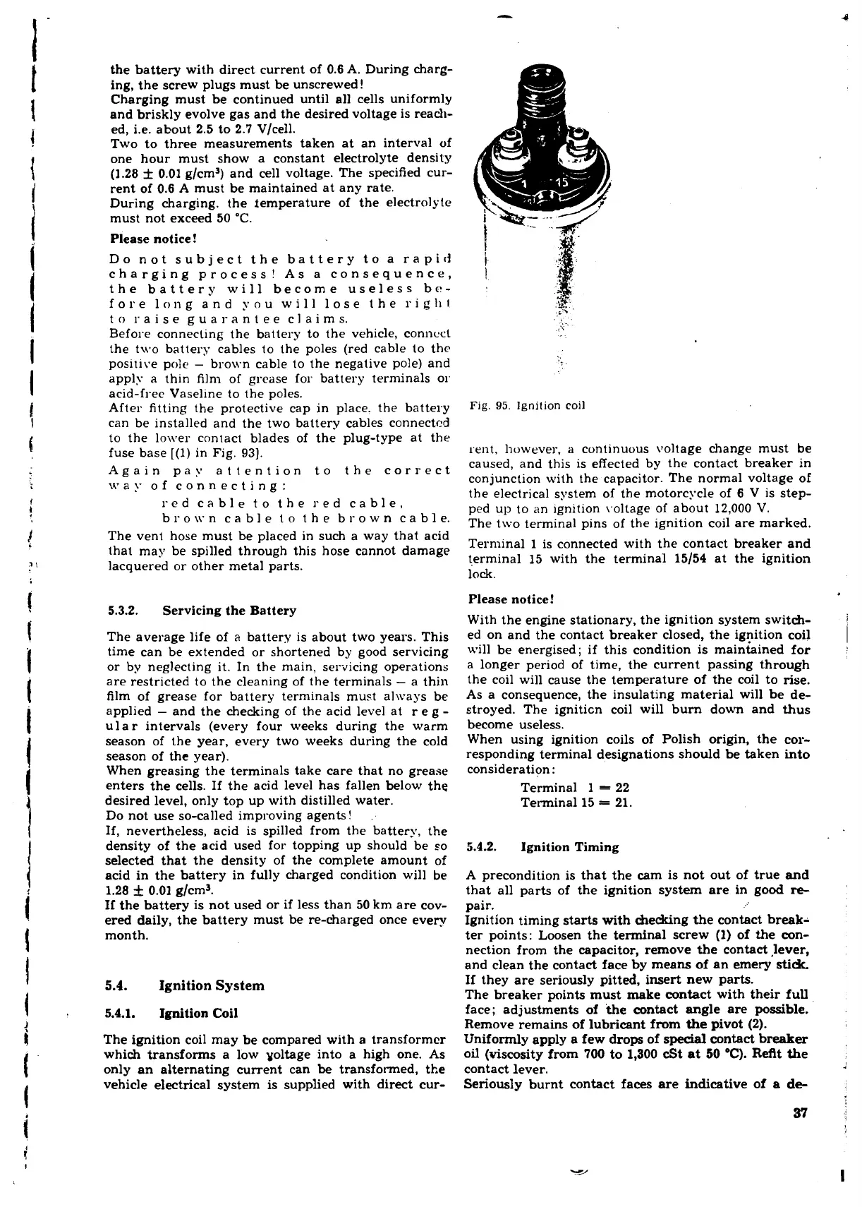
Fig.
95.
Ignition coil
rent, liuwever, a continuous voltage change must be
caused, and this is effected by the contact breaker in
conjunction with the capacitor. The normal voltage of
the electrical system of the motorcycle of 6 V is step-
ped up to an ignition \.oltage of about 12,000
V.
The t\vo terminal pins of the ignition coil are marked.
Terminal 1 is connected with the contact breaker and
terminal 15 with the terminal 15/54 at the ignition
lock.
Please notice!
With the engine stationary, the ignition system switch-
ed on and the contact breaker closed, the igpition coil
will be energised; if this condition is maintained for
a longer period of time, the current passing through
the coil will cause the temperature of the coil to rise.
As a consequence, the insulating material will be de-
stroyed. The igniticn coil will bum down and thus
become useless.
When using ignition coils of Polish origin, the cor-
responding terminal designations should
be
taken into
consideration:
Terminal 1
=
22
Terminal 15
=
21.
5.4.2. Ignition Timing
A precondition is that the cam is not out of true and
that all parts of the ignition system are in good
re-
pair.
Ignition timing starts with checking the contact break-
ter points: Loosen the terminal screw (1) of the con-
nection from the capacitor, remove the contact lever,
and clean the contact face by means of an emery
stidt
If they are seriously pitted, insert new parts.
The breaker points must make contact with their full
face; adjustments of the contact angle are possible.
Remove remains of lubricant from
the
pivot (2).
Uniformly apply a few drops of
special
contact breaker
oil (viscosity from
700
to 1,300 cSt
at
50
'C).
ReAt the
contact lever.
Seriously burnt contact faces are indicative of
a
de-
37
1
 Loading...
