5.2.1.
Adjustment
It should be underlined that a proper adjustment of
the regulator cut-out can only be carried out with
n
dynamo of the specified type which is
in
perfect work-
ing order on a test bench which is infinitely variable
within the speed range from
0
to about
6000
rpm.
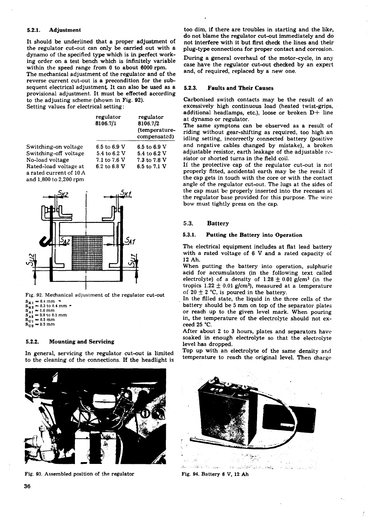
The mechanical adjustment of the regulator and of the
reverse current cut-out is a precondition for the sub-
sequent electrical adjustment. It can also
be
used as a
provisional adjustment. It must be effected according
to the adjusting scheme (shown in Fig.
92).
Setting values for electrical setting
:
Switching-on voltage
Switching-off voltage
No-load voltage
Rated-load voltage at
a rated current of
10
A
and
1,800
to
2,200
rpm
regulator regulator
8106.711 8106.712
(temperature-
compensated)
6.5
to
6.9
V
6.5
to
6.9
V
5.4
to
6.2
V
5.4
to
6.2
V
7.1
to
7.6
V
7.3
to
7.8
V
6.2
to
6.8
V
6.5
to
7.1
V
Fig.
92.
Mechanical adjustment of the regulator cut-out
5.2.2.
Mounting and Servicing
In general, servicing the regulator cut-out
is
limited
to the cleaning of the connections. If the headlight
is
Fig.
93.
Assembled position of the regulator
too dim, if there are troubles in starting and the like,
do not blame the regulator cut-out immediately and do
not interfere with it but flrst check the lines and their
plug-type connections for proper contact and corrosion.
During a general overhaul of the motor-cycle, in any
case have the regulator cut-out checked by an expert
and, of required, replaced by a new one.
5.2.3.
Faults and Their Causes
Carbonised switch contacts may be the result of an
excessively high continuous load (heated twist-grips,
additional headlamps, etc.), loose or broken D+ line
at dynamo or regulator.
The same
symptom can be observed as a result of
riding without gear-shifting as required, too high an
idling setting, incorrectly connected battery (positive
and negative cables changed by mistake), a broken
adjustable resistor, earth leakage of the adjustable
rc-
sistor or shorted turns in the field coil.
If the protective cap of the regulator cut-out is not
properly fitted, accidental earth may be the result if
the cap gets in touch with the core or with the contact
angle of the regulator cut-out. The lugs at the sides of
the cap must be properly inserted into the recesses at
the regulator base provided for this purpose. The wire
bow must tightly press on the cap.
5.3.
Battery
5.3.1.
Putting the Battery into Operation
The electrical equipment includes at flat lead battery
with a rated voltage of
6
V
and a rated capacity of
12
Ah.
When putting the battery into operation, sulphuric
acid for accumulators (in the following text called
electrolyte) of a density of
1.28
+
0.01
g/cm3 (in the
tropics
1.22
+
0.01
g/cm3), measured at a temperature
of
20
+
2
"C,
is poured in the battery.
In the filled state, the liquid in the three cells of the
battery should be
5
mm on top of the separator plates
or reach up to the given level mark. When pouring
in, the temperature of the electrolyte should not ex-
ceed
25
"C.
After about
2
to
3
hours, plates and separators have
soaked
in
enough electrolyte so that the electrolyte
level has dropped.
Top up with an electrolyte of the same density and
temperature to reach the original level. Then charge
Fig.
94.
Battery
6 V,
12
Ah
 Loading...
