or the line
31
from the "negative" terminal of thc
battery to the earth point is interrupted;
4.
the line from dynamo D+ to regulator D+ and
from regulator
61
to ignition lock
61
and control
lamp is interrupted
;
5.
the control lamp is blown;
6. the regulator cut-out is defective.
5.1.8.
Adjustable Resistor
Together with the regulator cut-out, the adjustable re-
sistor has the task to keep the desired voitage constant.
Current passes through the adjustable resistor at that
instant when the
regulating armature is in suspension
:late because in this position the adjustable resistor
and the excitation winding are connected in series.
In the lower position, the adjustable resistor is bridged
by the regulating armature and thus is of no impor-
tance to voltage regulation.
In the upper position. the armature has also no
func-
lion to fulfil because the excitation winding is short-
circulted and th~s the voltage breaks down.
If
the adlustablt
I
esistol. is blo\vn, this will be indi-
crtted b\. .in irl.~~gular firing ~,rder.
A
charred insulation
varnizh
on
t11c
iuL.lib
of thi' i~dj~~table ~xxiistol- and cav-
boniwd cuntacts
of
the 1.cgu1~tor \vill then be the proof.
When the charging conllol light flashes up
\\.bile
the
cnjilne
1s
running.
the
adjustable resistor may have
earth contact. \Vhen
;l
blown adjustabl~) resistol is
IT-
p1;tccd
by
a
ne\v
one.
first find the cause of the troublc
mless the ne\v resistor will
be
exposed to the same
hazard.
Another cause
may be a broken or loose
D+
line at
'he regulator or in the dynamo.
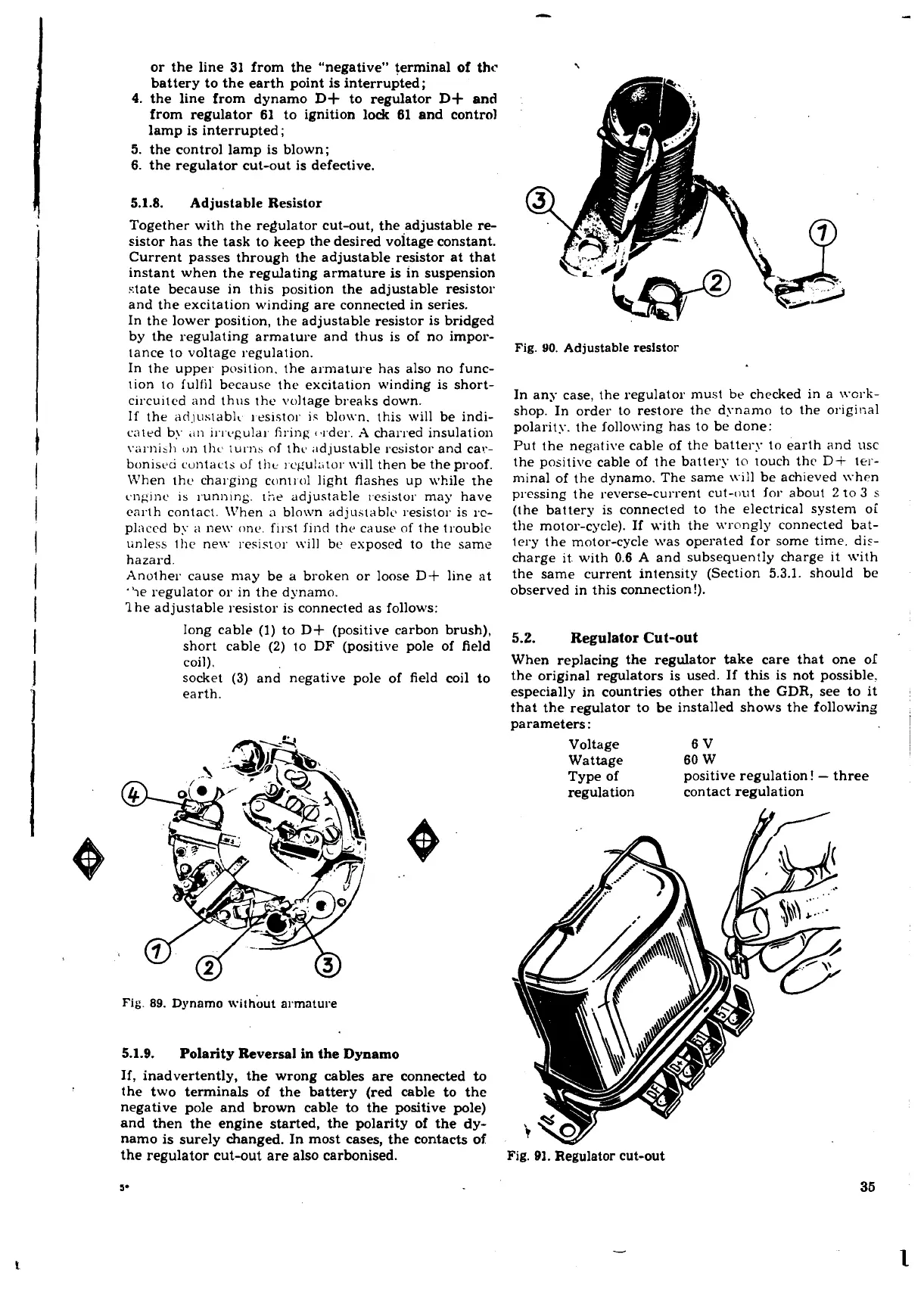
?he adjustable resistor is connected as follows:
long cable
(1) to
D+
(positive carbon brush),
short cable
(2)
to
DF
(positive pole of field
coil).
socket (3) and negative pole of field coil to
earth.
Fig.
89.
Dynamo with& armature
5.1.9.
Polarity Reversal
in
the Dynamo
If, inadvertently, the wrong cables are connected
to
the two terminals of the battery (red cable to the
negative pole and brown cable to the positive pole)
and then the engine started, the polarity of the dy-
namo is surely changed. In most cases, the contacts of
the regulator cut-out are also carbonised.
Fig.
90.
Adjustable resistor
In any case, the regulator must be checked in a \vcrk-
shop. In order to restore the dynamo to the origi~xl
polarity. the following has to be done:
Put the negative cable of the battery to earth and usc
the positive cable of the battery to touch thc
D+
ler-
mina1 of the dynamo. The same \\.ill be achieved \\hen
pressing the reverse-current cut-out for about
2
to
3
s
(the battery is connected to the electrical system oi
the motor-cycle). If with the wrongly connected bat-
lery the motor-cycle was operated for some time. dis-
charge it. with 0.6
A
and subsequently charge it with
the same current intensity (Section 5.3.1. should be
observed in this connection!).
5.2.
Regulator Cut-out
When replacing the regulator take care that one
01
the original regulators is used. If this is not possible.
especially in countries other than the
GDR,
see to it
that the regulator to be installed shows the following
parameters:
Voltage 6V
Wattage 60 W
Type of
positive regulation!
-
three
regulation contact regulation
Fig.
91.
Regulator cut-out
 Loading...
