5.1.6.
Servicing the Commutator
The commutator surface on which the brushes slide
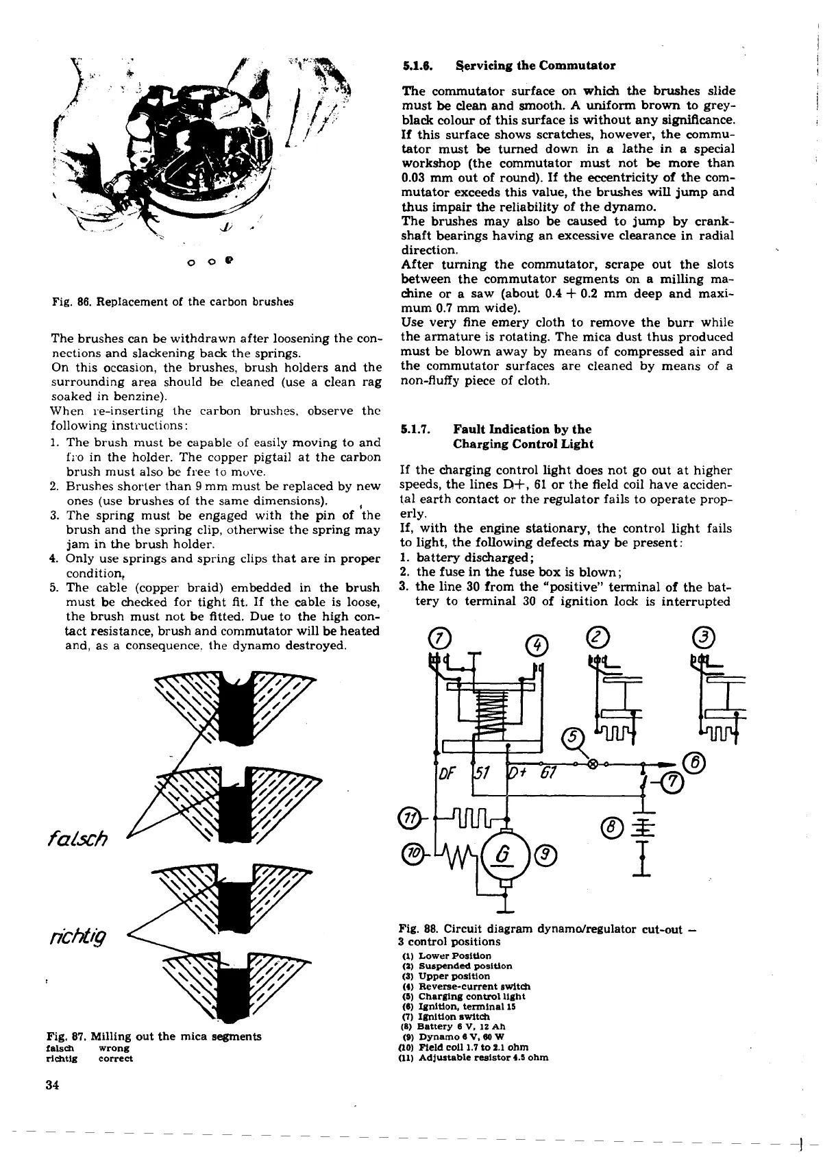
Fig.
86.
Replacement of the carbon brushes
The brushes can be withdrawn after loosening the con-
nections and slackening back the springs.
On this occasion, the brushes, brush holders and the
surrounding area should be cleaned (use a clean rag
soaked in benzine).
When re-inserting the carbon brushes. observe the
following instructions:
1.
The brush must be capable of easily moving to and
fro in the holder. The copper pigtail at the carbon
brush must also be free to move.
2.
Brushes shorter than
9
mm must be replaced by new
ones (use brushes of the same dimensions).
,
3.
The spring must be engaged with the pin of the
brush and the spring clip, otherwise the spring may
jam in the brush holder.
4.
Only use springs and spring clips that are in proper
condition,
5.
The cable (copper braid) embedded in the brush
must be checked for tight fit. If the cable is loose,
the brush must not be fitted. Due to the high con-
tact resistance, brush and commutator will be heated
and, as a consequence. the dynamo destroyed.
Fig.
87.
Milling out the mica segments
falsdl wrong
dchtlg correct
must
be
clean and smooth.
A
uniform brown to grey-
black colour of this surface is without any significance.
If this surface shows scratches, however, the commu-
tator must
be
turned down in a lathe in a special
workshop (the commutator must not
be
more than
0.03
mm out of round). If the eccentricity of the com-
mutator exceeds this value, the brushes will jump and
thus impair the reliability of the dynamo.
The brushes may also be
caused
to jump by crank-
shaft bearings having an excessive clearance in radial
direction.
After turning the commutator, scrape out the slots
between the commutator segments on a milling ma-
chine or a saw (about
0.4
+
0.2
mm deep and maxi-
mum
0.7
mm wide).
Use very fine emery cloth to remove the burr while
the armature is rotating. The mica dust thus produced
must be blown away by means of compressed air and
the commutator surfaces are cleaned by means of a
non-fluffy piece of cloth.
5.1.7.
Fault Indication
by
the
Charging Control Light
If the charging control light does not go out at higher
speeds, the lines
R+,
61
or the field coil have acciden-
tal earth contact or the regulator fails to operate prop-
erly.
If, with the engine stationary, the control light fails
to light, the following defects may be present:
1.
battery discharged
;
2.
the fuse in the fuse box is blown;
3.
the line
30
from the "positive" terminal of the bat-
tery to terminal
30
of ignition lock is interrupted
Fig.
88.
Circuit diagram dynamdregulator cut-out
-
3
control positions
(1)
Lower Position
(1)
Suspended positlon
(3)
Upper position
(4)
Reverse-current switch
(5)
Charging control light
(6) Ignition, terminal
15
(7)
Ignition switch
(8)
Battery 6
V.
12
Ah
(Q)
Dynamo 6
V.
80
W
(10)
Field coil
1.7 to 2.1
ohm
(11) Adjustable resistor
4.5
ohm
 Loading...
