dial to a whole number of degrees, if necessary. Then
turn bqck until the piston contacts the right-hand stop
and record the degrees (and minutes).
It follows that the T.D.C. is exactly in the centre of
the section through which the pointer
did not pass.
Record this number or mark it at the graduated dial
but do not displace dial or pointer!
Then, proceeding from the determined T.D.C. count
22"
45' to 23" 45' in the sense of rotation of the engine
and mark at the point thus found the f i
r
i
n
g
poi n t.
Then unscrew the stop for the piston and set the firing
point by means of a test lamp.
5.4.2.2.
Setting the Firing
Point
Fil.ing point:
3.0-0
s
mm before T.D.C. or
22" 45' to
23"
45' before T.D.C.
When setting outside the. vehicle, connect a
6
V
bat-
ter\.
interposing
a
1.2-W test lamp (2), with the po-
sitive pole to terminal "1" (A) and the negative poie
to
c~~rth (lamp flashes up lvhen the contact breaker
rlosrs).
If
setting in the vehicle. apply one terminal of the
lamp
(2)
to connection "I"
(A)
at the capacitor (or
coii:
LICI
rail) i~nd the second terminal to earth.
For the timing
operation
switch on the ignition.
\:'it11
;l;c,
29-50.801 ignition tinling gauge screwed in
pl;~ce. use the armature screw
(1)
to turn the piston
o\.~r the T.D.C.
-
the scale of the gauge automatically
adjusts itself to the T.D.C. Continue to turn the crank-
shaft in the sense of rotation of the engine until the
firing point is reached.
At this instant, the test lamp must flash up. If this is
not the case, loosen the two screws (3) and shift the
contact-breaker base plate sideways.
After setting. apply
a
few drops of special contact-
breaker oil to the lubricating felt pad. Adjust the pad
so that it just slightly contacts the
high-level portion
of the
cam.
Fig.
100.
Ignition timing with ignition getting gauge
If the pad contacts the full cam profile, the lubricant
will be pumped out of the pad before long, the dry
felt then rises the temperature of the cam track
-
premature wear of the nose at the contact lever will
be
the result
!
The sparking-plug in essence consists of three parts.
These are the central electrode and the carrier which
also acts as the earth electrode. The spark jumps over
between these two electrodes, igniting the fuel-air mix-
ture. The third part of the plug is the insulating body
or insulator. It must have a high dielectric strength.
To ensure this dielectric strength at all times, the
sparking-plug must be treated gently. By improper
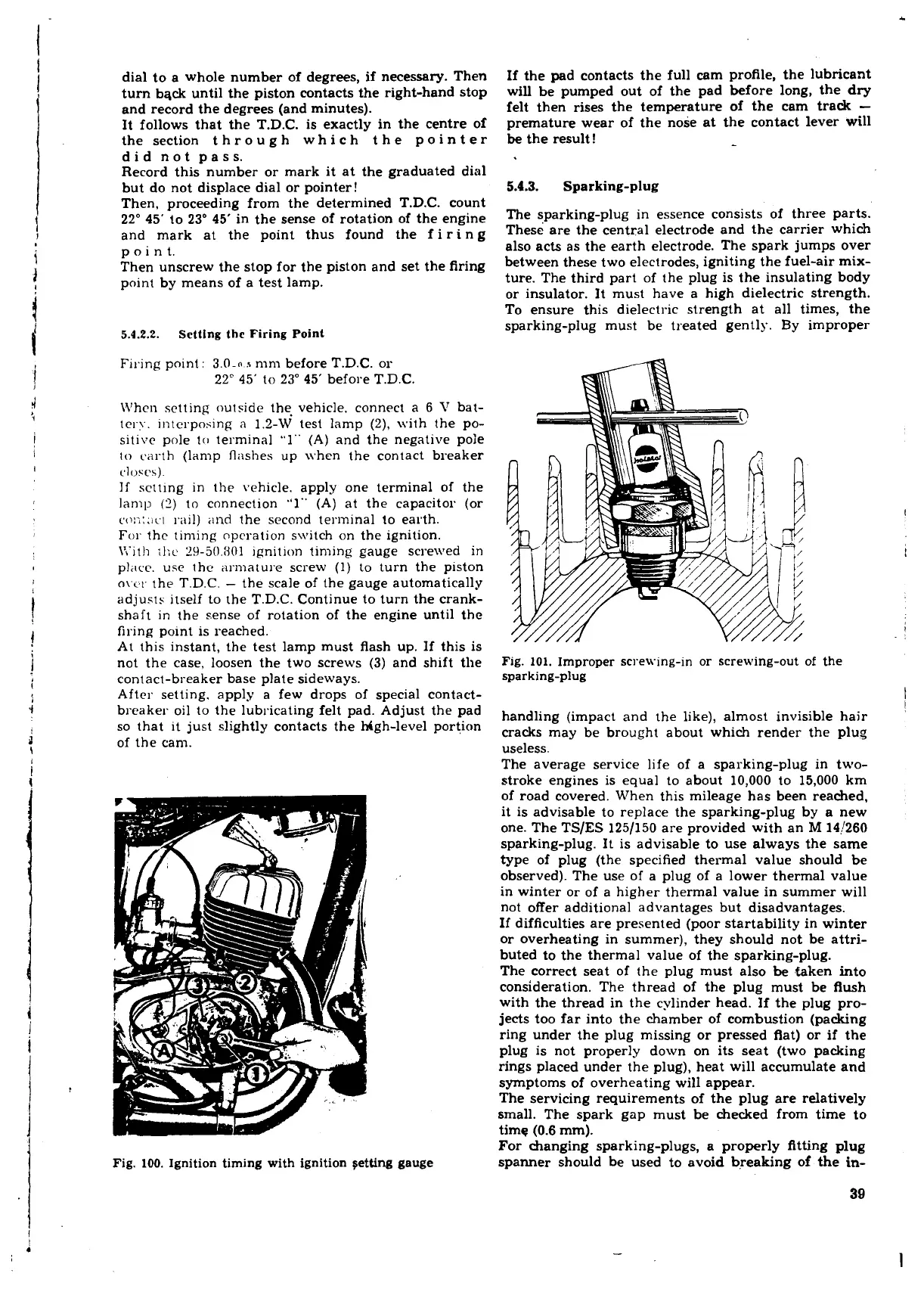
Fig.
101.
Improper screwing-in or screwing-out
of
the
sparking-plug
l
l
handling (impact and the like), almost invisible hair
cracks may be brought about which render the plug
useless.
The average service life of
a
sparking-plug in two-
stroke engines is equal to about 10,000 to 15,000 km
of road covered. When this mileage has been reached,
it is advisable to replace the sparking-plug by a new
one. The TSlES 1251150 are provided with an
M
14!260
sparking-plug. It is advisable to use always the same
type of plug (the specified thermal value should be
observed). The use of a plug of a lower thermal value
in winter or of a higher thermal value in summer will
not offer additional advantages but disadvantages.
If difficulties are presented (poor startability in winter
or overheating in summer), they should not be attri-
buted to the thermal value of the sparking-plug.
The correct seat of the plug must also
be
faken into
consideration. The thread of the plug must be flush
with the thread in the cylinder head. If the plug pro-
jects too far into the chamber of combustion (packing
ring under the plug missing or pressed flat) or if the
plug is not properly down on its seat (two packing
rings placed under the plug), heat will accumulate and
symptoms of overheating will appear.
The servicing requirements of the plug are relatively
small. The spark gap must be checked from time to
time
(0.6
mm).
For changing sparking-plugs, a properly fitting plug
spanner should be used to avoid breaking of the
in-
 Loading...
