FOI.
hi,
purpose. thc apnnncl
is
scre\ved into th(,
h1
27
X
2
thread of the guide tubes. The assenlblerl
position of the guide tubes must be marked bp coloui~
dots bclo\v the lo\ver clamping head before disman-
tling.
To
iacil~tate I-e-assembling.
it
is
advisable, immediately
after ha\.ing ~.emoved one telescopic unit, to insert an-
other guide tube
or a suitable piece of pipe with a di-
ameter of anything between
31.7
and
31.8
mm form
the bottom and in order that the rubber pads for the
headlamp holder \\.ill not be dislocated.
For assenlbllng and disassembiing only adequate tools
should be used. With makeshift tools, damage will be
caused and successful repairs \\rill not be ensured.
For
disnlantling a telescopic unit, it is to be clamped
at the spindle bush but not at the guide tube!
After 1.en1oving the protective cap or protective bush,
the threaded ring can be loosened by means of the
combined assembling spanner and the guide tube to-
gether with the lower slide bush and the damping
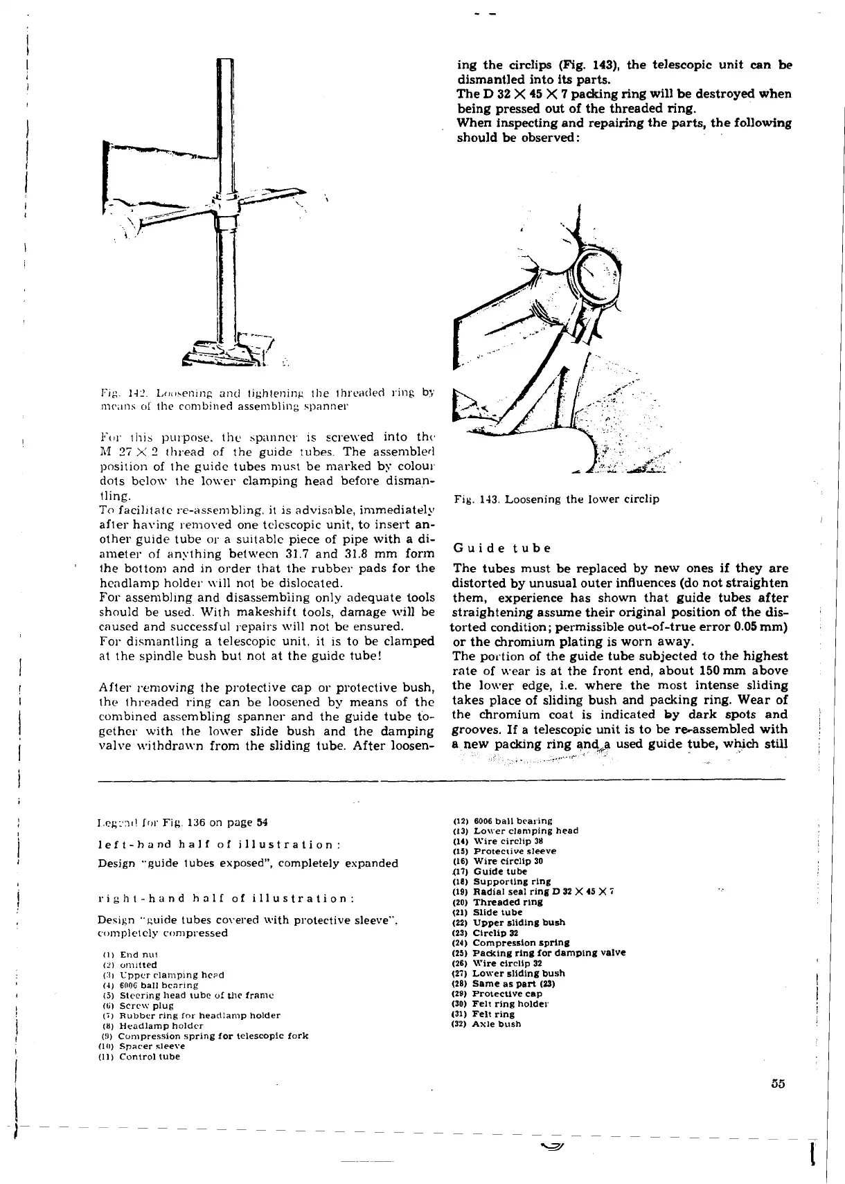
valve withdrawn from the sliding tube. After loosen-
ing the
circlips (Fig.
143),
the telescopic unit can
be
dismantled into
its
parts.
The
D
32
X
45
X
7
packing ring will be destroyed when
being pressed out of the threaded ring.
When inspecting and repairing the parts, the following
should be observed
:
.
.
Fig.
143.
Loosening the lower circlip
Guide tube
The tubes must be replaced by new ones if they are
distorted by unusual outer influences (do not straighten
them, experience has shown that guide tubes after
straightening assume their original position of the dis-
torted condition; permissible out-of-true error
0.05
mm)
or the chromium plating is worn away.
The portion of the guide tube subjected to the highest
rate of wear is at the front end, about
150
mm
above
the lower edge, i.e. where the most intense sliding
takes place of sliding bush and packing ring. Wear of
the chromium coat is indicated
by
dark spots and
grooves. If a telescopic unit is to be reassembled with
a
new packing ring and+a used guide tube, which still
,
.
.
.
r
I,egr.:11! lrw
Fig.
136
on page
51
left-hand half
of
illustration:
Design "guide tubes exposed", completely espanded
right-hand half of illustration:
Desijin "cuide tubes co\.ered with protective sleeve".
completely compressed
(1)
~nd
nil!
(2)
onl~tted
(31
Uppcr
rlamplng
he~d
(4)
600'3
ball
bcarlng
(5)
Slcer~ng
head
tube
of
the
franic
(G)
scre\'.'
plug
(7)
Rubbcr
ring
for
headlamp
holder
(8)
Headlamp
holder
(!l)
Compression
spring
for telescopic
fork
(10)
Sparer
sleeve
(11)
Control
tube
(12)
6006
ball
bearing
(13)
Lower
clamping
head
(14)
Wire
circlip
38
(15)
Protective
sleeve
(16)
Wire
circlip
30
417)
Guide
tube
(18)
Supportlng
rlng
(19)
Radial seal
ring
D
32
X
45
X
i
(20)
Threaded
ring
(21)
Slide
tube
(22)
Upper sliding bush
(23)
CircliD
32
(24)
Compression spring
(25)
Padring
ring
for
damping
valve
(26)
Wire
circlip
32
(27)
Lower sliding bush
(28)
Same
as
part
(D)
(29)
Protective cap
(30)
Felt
ring
holder
(31)
Felt
ring
(32)
Axle
bush
 Loading...
