is in perfect working order, it is advisable to mount
the guide tube in such a manner that it is displaced
through
180" with respect to its former assembled
pc+
sition.
When reassembling telescopic units which were not
disassembled into their component parts, it
is
advisa-
ble, however, to At the guide tube in their original po-
sition in the assembly. Over its entire length, the guide
tube must be free from impact marks, grooves and
other surface irregularities
to ensure that the packing
ring will not be damaged when it is slipped on the
assembly. Surface irregularities must
be
removed by
a fine-grained oilstone moved longitudinally.
Upper sliding bush
The required measure of the hole is 31.850 to
31.889 mm. Experience has shown that limited wear
occurs so that replacement practically is not necessary.
The inner surface of the hole partly exhibits a non-
uniform appearance caused by a small eccentricity in
the position of the assembled components parts due to
manufacture; this is not associated with any drawback,
however.
Lower sliding bush
The outer diameter is 37.875 to 37.900 mm. This part
is also subjected to a low wear rate so that replacement
\vill become necessary only after 30,000 to 50.000 km
of road operation.
The given axial play of the sliding bush between the
circlips of the guide tubes can lead to a clicking sound
emitted from the telescopic fork on the move which
has no influence on the function. This insignificant flaw
can be removed by fitting an adequate spacer between
circlip and lower edge of the sliding
blsh to remove
this axial play. This washer must exactly fit on the
guide tube, diameter 31.7 mm, and its external dia-
meter must not exceed
35.5
mm to prevent these
washers from rubbing against the inner surfaces of the
sliding tubes at any rate.
process would be destroyed and lead to an unusual
wear of the lower sliding bush.
If, by extraordinary conditions (foreign particles
or.
similar things), the interior surface of the sliding tube
is damaged, the surface may be restored
to proper
working order by honing (in a manner similar to that
used in finishing the cylinder bore). The required di-
mension of the diameter of the sliding tube hole
is
38.00 to 38.05 mm.
Damping valve
In this part, only an insignificant amount of wear is
involved so that a replacement of the components is
practically not necessary.
The sealing rings for the damping valve. made of
piston ring material, must be free to move easily. free
from burr and absolutely clean. Small contaminatio~s
may easily lead to jamming of the sealing ring or to
leaks in the valve.
Fig.
145.
Pressing the packing ring
into
the 1111.eaded rin;
by
means
ol
the combined assembling spanner
(~n
a vicc
or
under
a
hand-lever press)
In
ordcr that the packing ring is not damaged when
pressed into the threaded ring. the combined assern-
Sliding tube
The surface of the hole exerts a great influence on the
ease of motion and wear of the interior of the telescop-
ic fork. The drilled hole is not mechanically finished
because by emery grinding or similar processes the
ex-
tremely smooth surface obtained in the manufacturing
Fig.
144.
Combined assembling spanner for pressing the
packing ring into the threaded ring
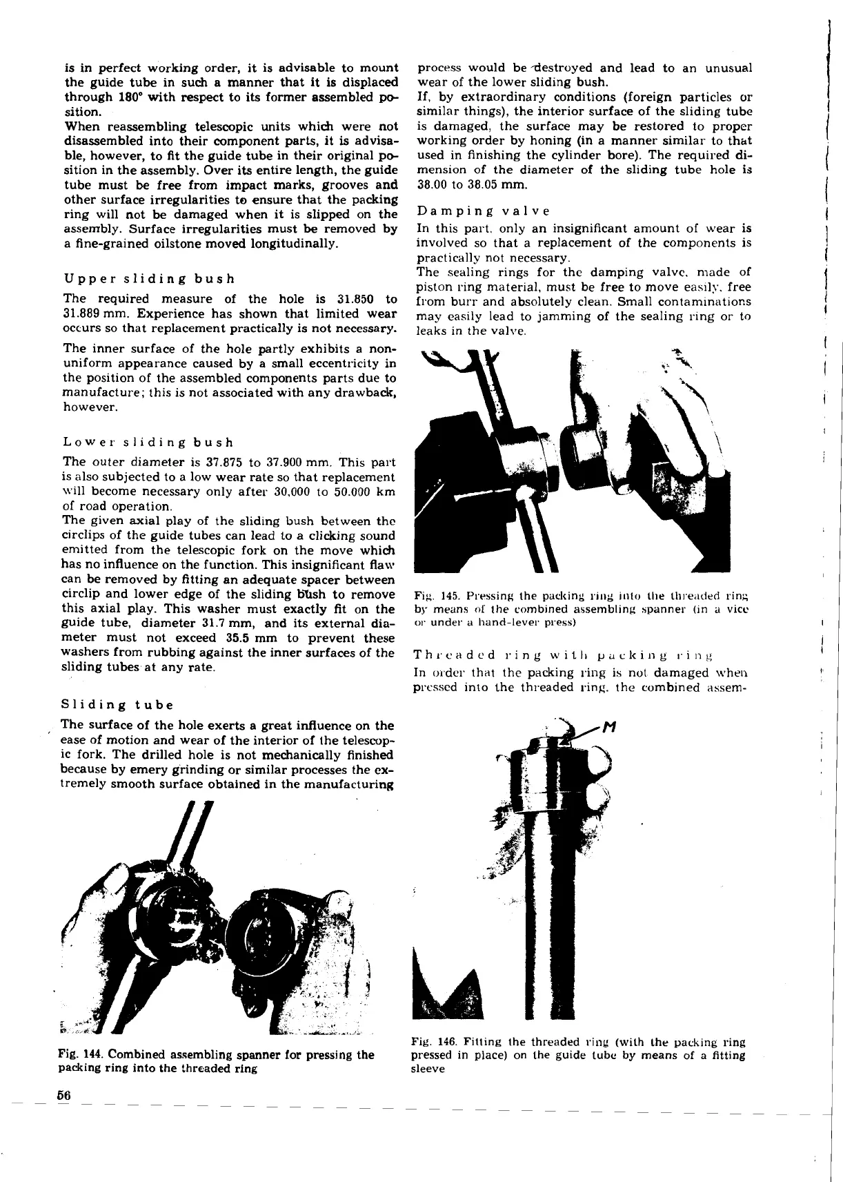
Fig.
146.
Fitting the threaded ring (with Lhe
packing
ring
pressed
in
place) on the guide tube by means
of
a
fitting
sleeve
 Loading...
