11 of 28
www.NabcoEntrances.com AcusensorMInstallaonManual
Rev 8-25-17 P/N C-00187
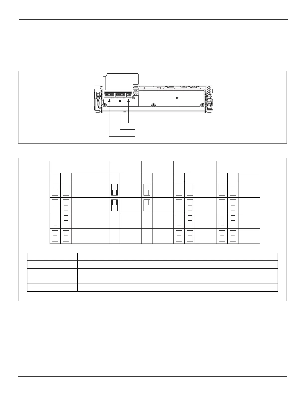
1. Turn OFF power.
2. Li the resusable protecon ap located on the Le hand side of Acusensor M.
a. Underneath the ap are three groups of Switches.
DN 1559
Switches 1-8
Switches 9-16
Switches 17-20
Figure 4 Switch Settings
b. The backside of Flap shows a diagram for how to set switches 1 thru 8.
DN 1560
Opera on Mode Output
Logic
Input
Logic
Width (L) Width (R)
12 345678
# Normal #N.O. # High #6 #6
Doorway 2 N.C. Low 5 5
* Doorway 1 4 4
First Row Off 3 3
#Default Se ng * Install Sensors on both sides of the Door
Opera on Mode Determines what part of the Presence Detec on Area (grid) is being monitored.
Output Logic Normally Open/Normally Closed
Input Logic Please refer to “Input Logic” Sec on
Width (L) Adjusts width of Presence Detec on Area (grid) on the Le Side of Door independently
Width (R) Adjusts width of Presence Detec on Area (grid) on Right Side of Door independently
Figure 5 Switch Setting Diagram located under Flap