15 of 28
www.NabcoEntrances.com AcusensorMInstallaonManual
Rev 8-25-17 P/N C-00187
DN 1561
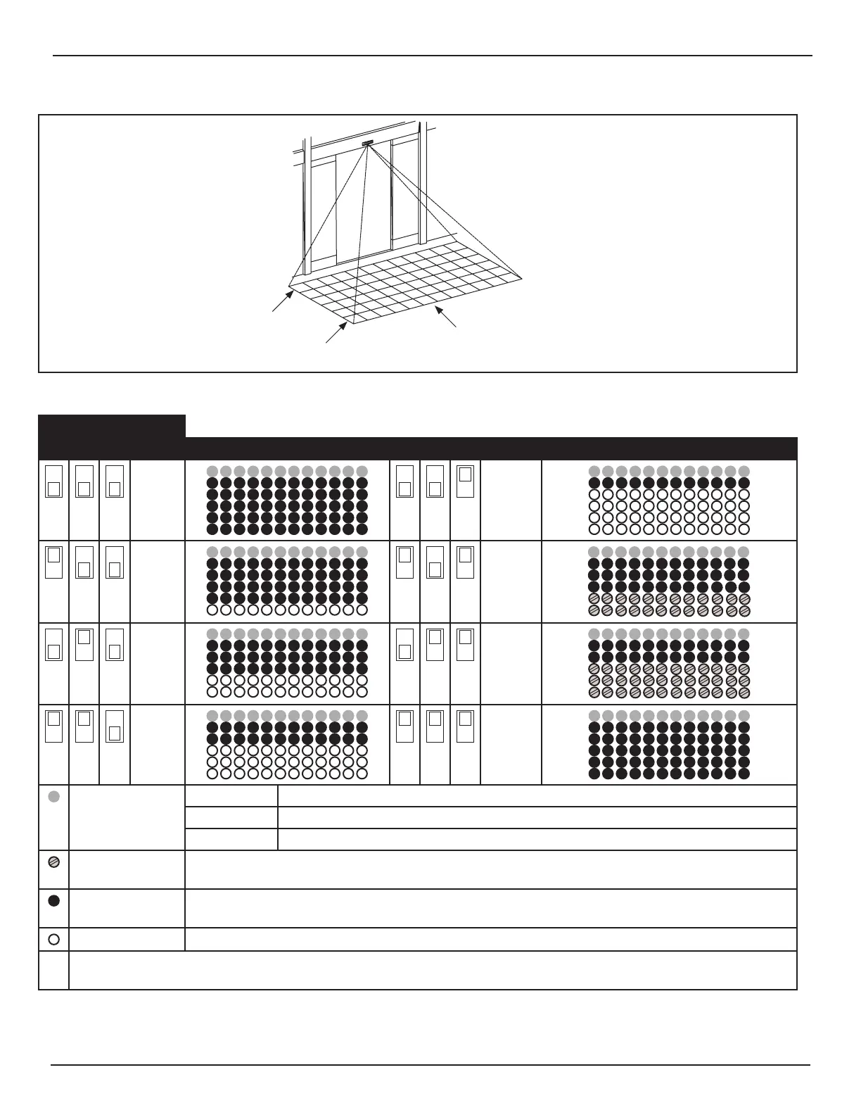
Presence Detec on Area
Row 1
Row 6
Note:
Row 1 is the Threshold Area
Figure 9 Presence Detection Area
Table 9
Depth
9 10 11 Detection Area Diagram 9 10 11 Detection Area Diagram
6 2
5 5-6 ECO
4 4-6 ECO
3 *Area
Check
Operaon Mode Normal This row is acve, but not applied to the monitoring funcon.
Doorway 1 This row is acve, and is applied to the monitoring funcon.
1st Row OFF Inacve
ECO Mode X Direconal presence detecon. For detailed informaon please refer to Subsecon 6.a.a.
X Same Depth Rows are Acve.
No Monitoring X These rows are acve, but not applied to the monitoring funcon.
X Depth Rows Acve.
Inacve Depth Rows are not Acve.
* Used for adjusng detecon area depth and conrming test command input, during installaon only. For detailed informaon
please refer to Subsecon 6.a.b.