13 of 28
www.NabcoEntrances.com AcusensorMInstallaonManual
Rev 8-25-17 P/N C-00187
In the event a Self Diagnosc Error occurs, the door will not open. Instead the Sensor LED will illuminate a blinking Red Light (1Hz)
indicang an Error.
Note: Ensure both the Acusensor M and the Control is set for N.O. or N.C.
Table 7 High Setting vs Low Setting
Input Logic
4 Description
High +input Connects to +voltage
- input Connects to Output, regardless of Switch 4 Seng.
X U30 FUNCTION (6) seng should be No
X Opus seng should be “Sensor Monitoring N.O. (Normally Open)
Low +input Connects to +voltage
- input Connects to Output, regardless of Switch 4 Seng.
X U30 FUNCTION (6) seng should be “Yes”.
X Opus seng should be “Sensor Monitoring N.C. (Normally Closed)
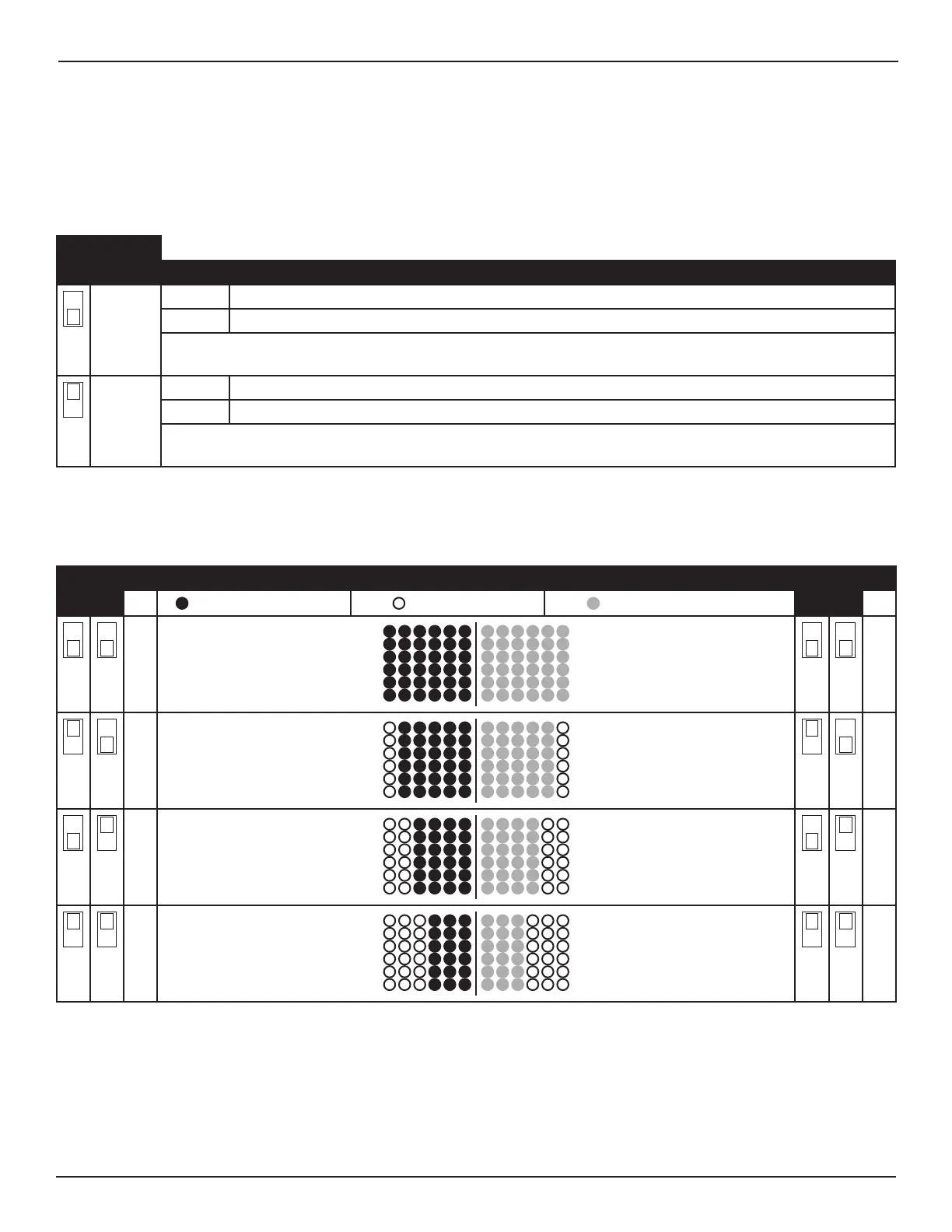
Note: On swing and fold doors, set width paern as narrow as needed to avoid detecon of the door in the open posion.
Table 8 Presence Detection Area
Width (L) Width Area Diagram Width (R)
5 6
= Acve Area Le Side = Inacve Area = Acve Area Right Side
7 8
6 6
5 5
4 4
3 3