8 of 28
Acusensor M Installaon Manual www.NabcoEntrances.com
P/N C-00187 Rev 8-25-17
Shut OFF the installation site, branch Circuit Breaker. Failure to do so may result in serious
personal or fatal injury. When uncertain whether power supply is disconnected, always verify
using a voltmeter.
All high voltage electrical connections must be made by licensed electricians according to
National and Local electrical codes/regulations.
Permanent wiring shall be employed as required by local codes.
Keep all Incoming 120 VAC wiring separate from low voltage wiring within Header. 120 VAC
Power wires must be routed (separate from other wiring) located near the top of inside Header.
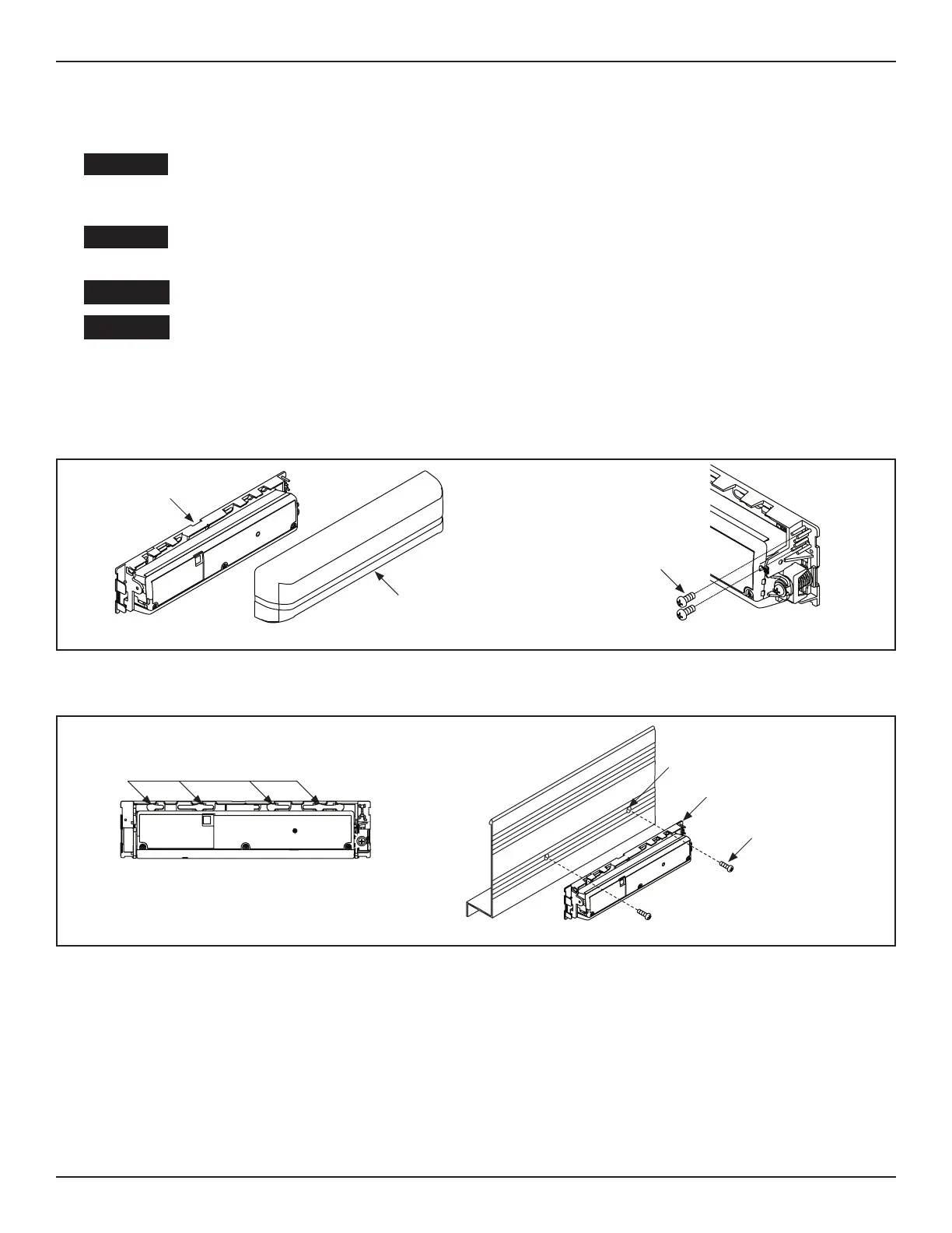
1. Turn OFF power.
2. Remove Cover from Sensor.
3. Remove (2) #10 x 1/2 inch Phillips Panhead screws from the cradles.
DN 1574
#10 x 1/2”
Phillips Head
Screw
Sensor
Cover
Figure 1 XXXX
4. Line up the predrilled screw holes located on the Mounng Plate with predrilled screw holes on the Header Cover.
5. Secure the Sensor to the Header Cover with (2) #10 x 1/2 inch Phillips Panhead screws.
Predrilled
Screw Holes
Predrilled Screw Holes
Sensor
DN 1575
#10 x 1/2”
Panhead Screw
Figure 2 Recessed Track
Note: The Angled Spacer is an opon that is sold separately. To do so, please call Customer Service at 1-888-679-3319.
1. Turn OFF power.
2. Remove Cover from Sensor.
3. Seat the Sensor inside the Angled Spacer.
a. The at side of Angled Spacer must bu up against the Header Cover.
4. Align the predrilled screw holes located on the Mounng Plate with the predrilled screw holes located on the Angled Spacer.
5. Secure the Sensor to the Header Cover with (2) #10 x 5/8 inch Phillips Panhead screws (supplied with the Angled Sensor Kit.
a. Do not use (2) #10 x 1/2” Phillips Panhead screws that were supplied with the Acusensor M kit.