20 of 28
Acusensor M Installaon Manual www.NabcoEntrances.com
P/N C-00187 Rev 8-25-17
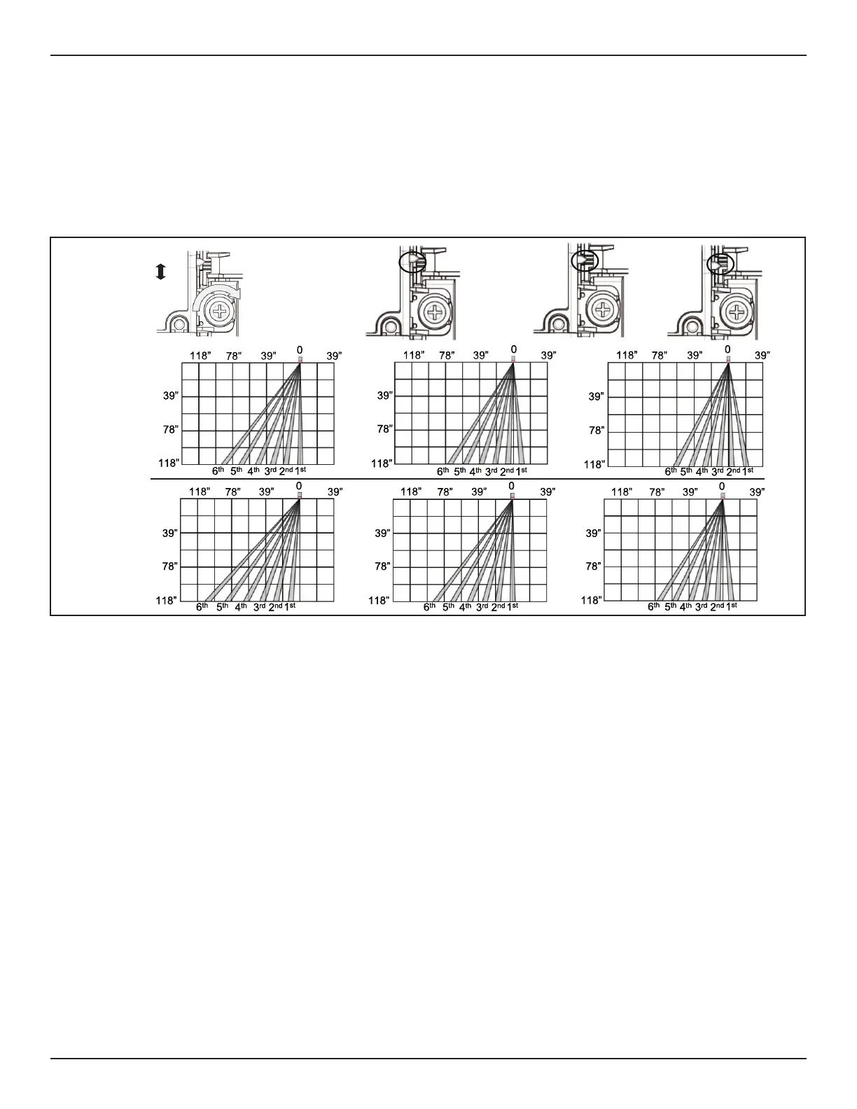
3. Turn the Area Adjuster unl the preferred Depth is achieved.
a. One half turn of the Area Adjuster:
X Without an Angled Spacer is almost equivalent to (1) degree.
(1) degree = 1.57 inches (40mm) if the Sensor mounting height is 87 inches (2.2m)
X Adding the Angled spacer (sold separately) adds an additional 5 degrees.
b. As the phillips head screw is turned, the Degree Indicator Lever will move from (0 to -10 degrees).
DN 1566
# 0 degree
0 degree
-10 degree
Minus
Direc on
-5 degree
-10 degree
# = Default
Without
Angled Spacer
With
Angled Spacer
1. Flip Switches 9, 10, and 11 UP.
2. Turn ON Power. Turn the Area Adjuster unl Depth Row (1) can be detected within (5) inches from the face of Door.
a. To do so, walk within the presence detecon area unl the LED illuminates a Red light.
b. The Red light indicates that Depth Row (1) is detecng.
1. Flip Switches 9, 10, and 11 UP.
2. Turn ON Power. Locate the center of Depth Row (1 and 2).
a.
Turn the Area Adjuster until Depth Row (2) can be detected within (5) inches from face of Door.
a. Depth Row (2) should not become part of the Threshold.
X Detection must occur to within (5) inches of the face of the door.
X The pattern needs to be moved out if the door itself is being detected.
X The pattern needs to be moved in if there is a loss of detection at any point greater that (5) inches from the face
of the door.