FP0 RTD Unit
Specifications
3. Until conversion data is ready after the initial startup, the digital
value shows 8191 or 16383. These are not temperature data. Program
in such a way that these values are not interpreted as temperature
data.
4. These are the settings of the input channel selection switch.
5. The control unit reads data from 2 channels in one scan. Read data
by using the programs described above.
6. This address applies when the FP0 RTD unit is installed as
expansion unit no. 1.
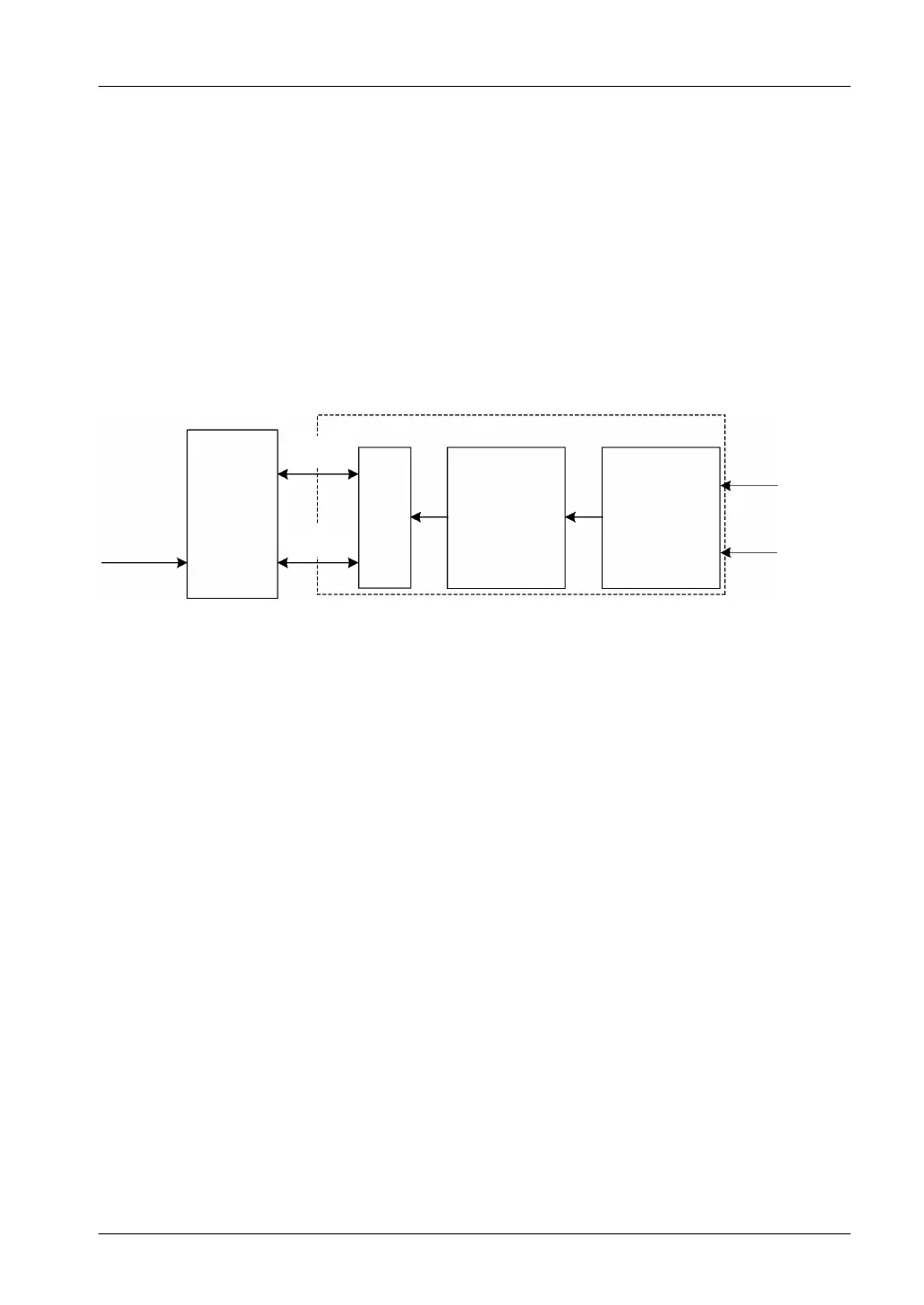
Block diagram
FP0/FP
CPU
24V DC
(increased
amount: max. 25mA)
Bus
+5V
I/F
Analog
input
circuit
PhotoMos
relay channel
switch circuit
FP0-RTD6 unit
CH0
CH5
to
23
 Loading...


