67
English
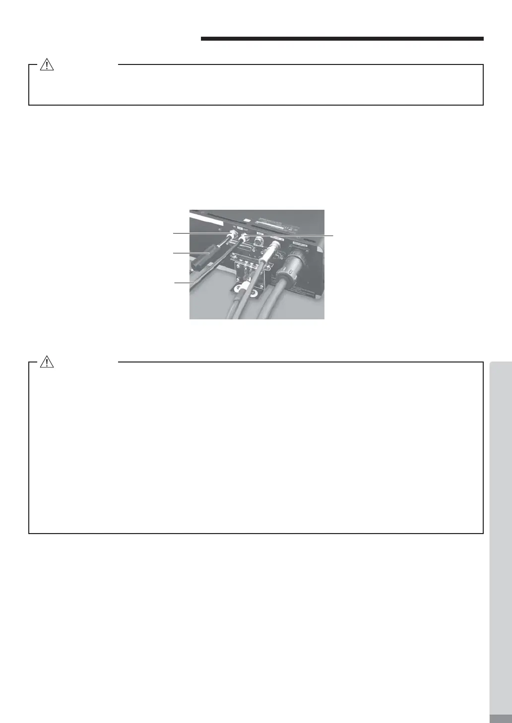
13. AIR HOSE CONNECTION
(1)
Insert the provided ȭ6mm Air Hose (2m) with Filter (CONTROLLER's standard accessories) from the Air Line
Kit into the Air Input Joint on the rear of the CONTROLLER .
(2) Insert one end of the provided ȭ6mm cooling Air Hose (Motor Cord's
standard accessories
) into the back of
the motor.
(3) Insert the other end of the ȭ6mm cooling Air Hose (Motor Cord's
standard accessories
) into the Air Output
Jo
int on the rear of the CONTROLLER .
(4) Regulate air pressure between 0.2 - 0.35MPa (29.0 - 50.8psi).
Air Input Joint
ȭ
6mm Air Hose (2m)
with Filter
ȭ
6mm cooling Air Hose
(Motor Cord
'
s standard
accessories)
Air Output Joint
Fig. 19
CAUTION
When not using NAKANISHI Air Line Kit, make sure that the incoming air supply is dry, clean and
properly regulated.
CAUTION
・The Air input joint, is designed to accept cooling air between 0.2 - 0.35MPa (29.0 - 50.8psi). If the
air pressure is too low, the CONTROLLER will not operate and an Error code will be generated.
Set the air pressure 0.35MPa (50.8psi) when using the motor spindle for continuous use.
・The cooling air also provides air purge protection to the motor spindle. If the Main Power Switch
is turned OFF, th
e cooling air will continue to À ow.
・Do not make any sharp bends in the air hose, or pull on the hose as this can cause the hose to
break, cut off the air supply or weaken the hose over time resulting in deterioration of the motor
and spindle.
・Never supply over regulated air pressure. There is a possibility to damage to the air detection
sensor inside the CONTROLLER.
・The air detect function within the CONTROLLER detects air input supply only. If the Air Out hose
is damaged from the CONTROLLER, it will not be able to detect the lack of cooling and purging
air to the motor spindle.